Cisco Collaboration and Contact Center Solutions - Messages for 2019 year

Aurus Blog

This blog is to share our expertise in Cisco UCM, UCCX/UCCE and Cisco Meeting Server

  • Archive

    «   April 2019   »
    M T W T F S S
    1 2 3 4 5 6 7
    8 9 10 11 12 13 14
    15 16 17 18 19 20 21
    22 23 24 25 26 27 28
    29 30          

Cisco Meeting Server Cluster: Scalability and Resilience deployment with meeting recording - PART 1

In this article, we’ll go into the details of CMS deployment in a failover cluster.

Theoretics

Basically, there are 3 types of CMS deployment:

  • Single Combined with all services running on a single server. In most cases, this deployment type is only applicable for systems with internal clients, or for small environments with scalability and redundancy restrictions not being crucial, or for the situation when CMS only carries out certain functions, such as CUCM special conferences.
    Approximate working scheme:
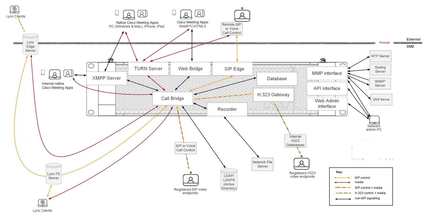
  • Single Split extends the previous deployment type with a separate server for external access. In outdated deployments this meant having CMS server deployed in DMZ (demilitarized zone) where external clients can access it, and another CMS server in core layer for the local clients. This specific deployment model is being replaced with so-called Single Edge type with Cisco Expressway servers that have (or will have) most firewall bypassing techniques, so clients won’t have to add a separate CMS edge server.
    Approximate working scheme:
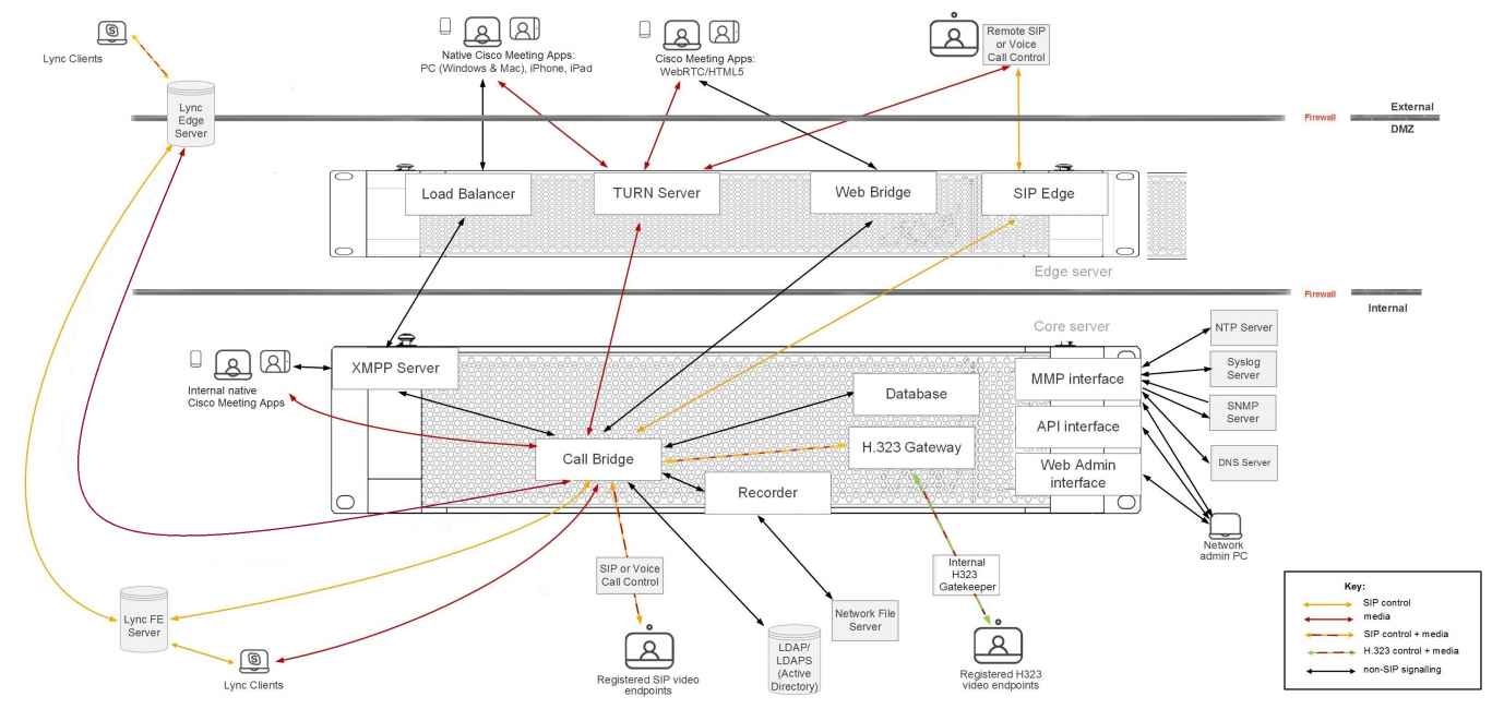
  • Scalable and Resilient type includes redundancy for each component, so the system can grow along with your needs up to the maximum capacity, providing redundancy in case of a failure. It also uses Single Edge conception to provide safe external access. This is the type we are going to discuss here. If we know how to deploy this type of cluster, not only will we understand other deployment types, but we also will be able to understand how to create CMS server clusters taking into account the potential requirement increases.

Before we discuss the deployment, we should clarify some basic ideas.

Basic CMS Program Components

  • Database: helps to combine some configurations, such as subscriber groups, user spaces and users. Supports high availability clustering only (one master).
  • Call Bridge: audio and video conferencing service that implements full control and processing of calls and multimedia processes. Supports high availability and scalable clustering.
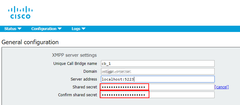
  • XMPP server: controls registration and authentication for the clients that use Cisco Meeting Application and/or WebRTC (real-time communication, used in browser), and intercomponent signaling. Supports high availability clustering only.
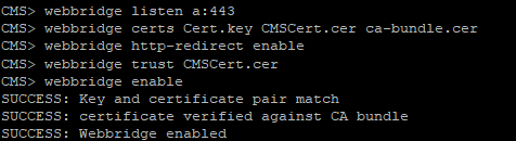
  • Web Bridge: provides WebRTC access for the clients.
  • Load balancer: provides a unified connection point for Cisco Meeting Applications in Single Split mode. It listens on an external interface and port for incoming connections. The load balancer also accepts incoming TLS connections from an XMPP server and transfers incoming TCP connections from external clients. It won’t be used in our scenario.
  • TURN server: provides firewall bypassing technique that allows launching our CMS behind a Firewall or NAT with external clients using Cisco Meeting App or SIP devices. It won’t be used in our scenario.
  • Web Admin: administration interface and API access (for Unified CM special conferences as well).

Configuration Approaches

Unlike most Cisco products, Cisco Meeting Server supports 3 configuration approaches, allowing you to perform any deployment type:

  • Command line interface (CLI), also known as MMP, can be used for initial configuration and certificate management.
  • Web admin: mostly for Call Bridge-related configuration tasks, especially for the configuration of a single non-clustered server.
  • REST API: for the most complicated configuration tasks and for clustered database-related tasks.

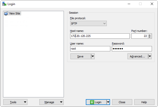
Besides that, you can use SFTP protocol for transferring files, including licenses, certificates and logs, to/from your CMS server.

Practice

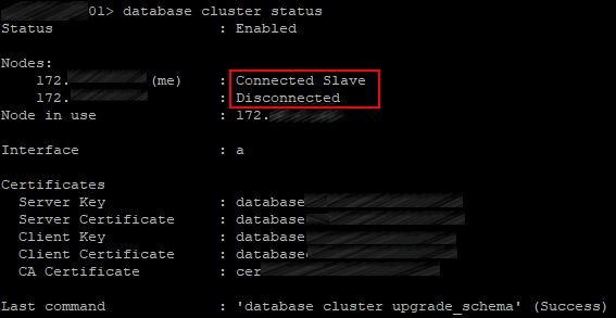
Cisco deployment guides say in cold print that in the context of databases, a cluster must consist of 3 nodes at least, since the new database Master selection mechanism can only work with an odd number of nodes:

Note: It's recommended to have an odd number of DB cluster nodes as it is important for the master selection and the active failover mechanism. Another reason for this is that the master DB node would be the node that has connections to the most of the DB in the cluster. You can have a maximum of 5 nodes in a DB cluster.

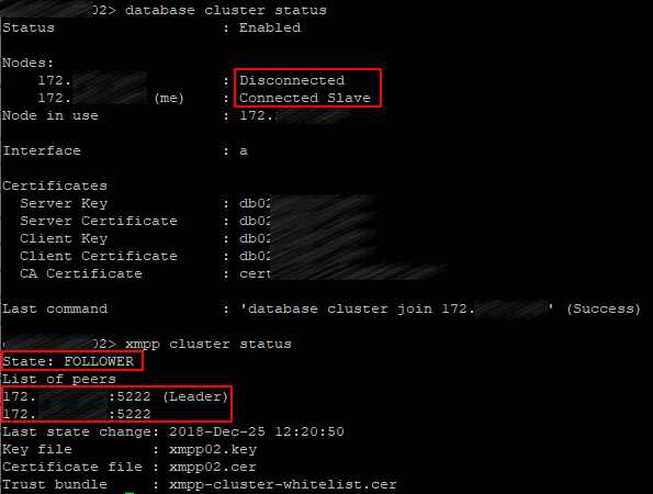
Indeed, as practice shows, 2 cluster nodes are not enough. The master selection snaps into action at the Master reset, and a Slave server becomes Master only after a rebooted server launches. However, if a Master server goes down in a cluster of two servers, then the Slave won’t become a Master. And if the Slave goes down, then the remaining Master will become a Slave, too.

Speaking of XMPP, a cluster should consist of 3 servers, indeed. If you stop XMPP service on the server that has XMPP in Leader status, then XMPP will stay in Follower status on the remaining server, and Call Bridges will be disconnected, because a Call Bridge can only connect to XMPP with Leader status. And this is critical, because no calls will go through.

These deployment guides also show a cluster with a single XMPP server.

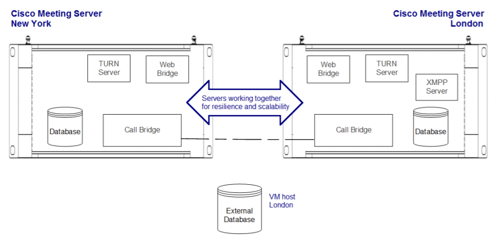
In view of the aforementioned, it’s clear: it works in failover mode.

In our case, XMPP server will be running on all three nodes.

Suppose that all three servers are up.

DNS Records

Before we proceed to the servers’ configuration, the following A and SRV DNS records must be created:

Record typeRecordDescription

A

servername-01.example.com
servername-02.example.com
servername-03.example.com
Resolving the name of each server in our cluster into its IP address.
A join.example.com
join.example.com
join.example.com
Three identical records resolved into the corresponding servers’ IP addresses. Users can enter this DNS name in a browser to access a conference from web.

SRV

_xmpp-client._tcp.conf.example.com
Three identical records referring to A records: servername-0x.example.com, allowing the servers’ port 5222. Cisco Meeting App clients use these records to find XMPP server.

SRV

_xmpp-component._tcp.conf.example.com
Three identical records referring to A records: servername-0x.example.com, allowing the servers’ 5223 port. Call Bridges use these records to detect XMPP server, if it is not defined explicitly.

Note that our DNS records have 2 domains: example.com and conf.example.com. Example.com can be used in URIs by all subscribers of Cisco Unified Communication Manager (which most likely is or will be used in your infrastructure). Or: example.com is the same domain that is used for email addresses. Or: Jabber client on your notebook can have the following URI: user@example.com.

Conf.example.com is the domain to be configured for all Cisco Meeting Server users. The Cisco Meeting Server domain will be conf.example.com, and Jabber users should use user@conf.example.com URI to log it to Cisco Meeting Server.

Basic Configuration

The configuration process will be described for a single server, but it should be performed for each server in a cluster.
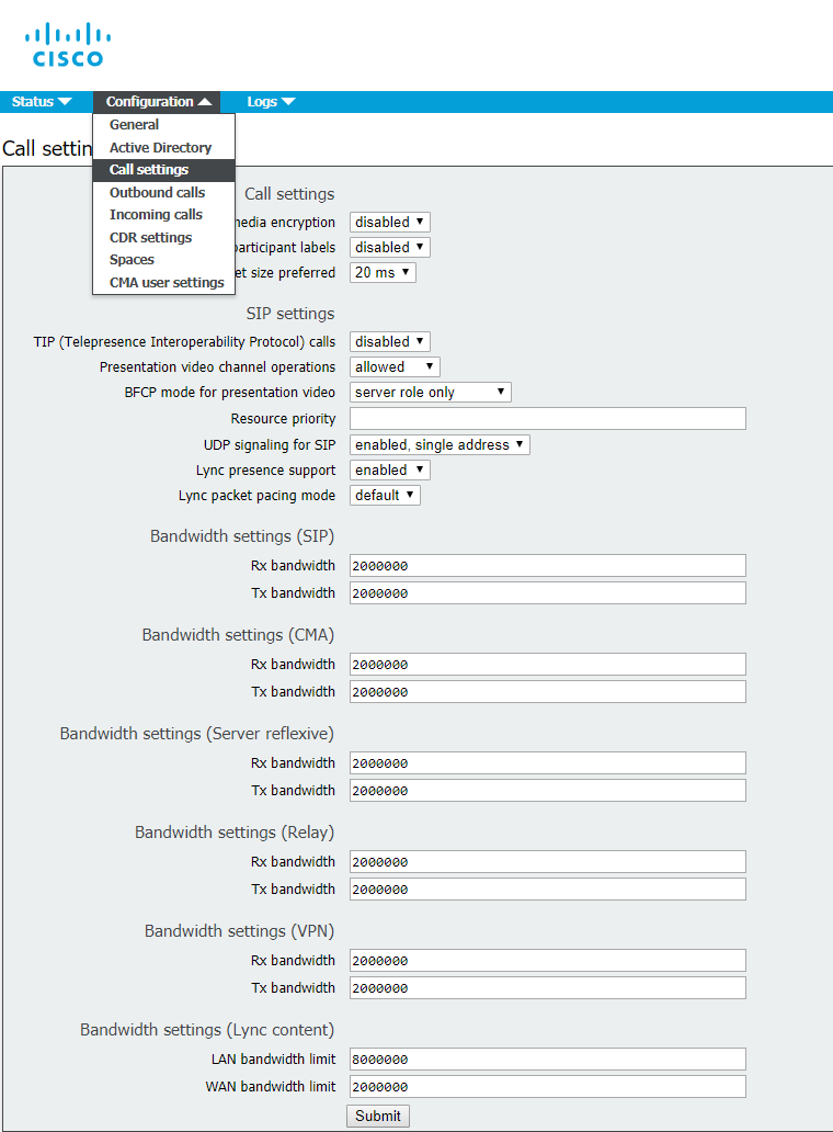
QoS

Since CMS produces real-time traffic that is sensitive to delays and packet loss, in most cases it’s recommended to set up quality of service (QoS). CMS supports marking packets with DSCP (differentiated services code points). DSCP-based traffic prioritizing depends on the way the traffic is processed by the network components in your infrastructure. We are going to configure our CMS with typical DSCP prioritizing that is based on best QoS practices.

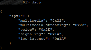
Enter the following commands on each server:

dscp 4 multimedia 0x22
dscp 4 multimedia-streaming 0x22
dscp 4 voice 0x2E
dscp 4 signaling 0x1A
dscp 4 low-latency 0x1A

So, all video traffic will be marked with AF41 (DSCP 0x22), all voice traffic will be marked with EF (DSCP 0x2E), other low-latency traffic types, such as SIP and XMPP, will be marked with AF31 (DSCP 0x1A).

Let’s check:

NTP

Not only is network time protocol (NTP) important for providing precise timestamps for the calls, but also for certificate verification.

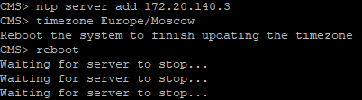
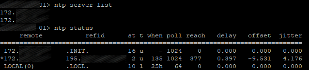
Use the following command to add your NTP servers:

ntp server add <server>

In our case, there are two of them, so the command will be executed twice.

Let’s check:

Set the time zone for your server.
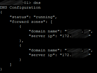
DNS

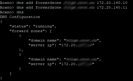
Use the following command on CMS to add DNS servers:

dns add forwardzone <domain-name> <server ip>

In our case, there are two of them, so the command will be executed twice.

Let’s check:

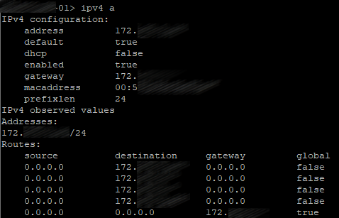
Network Interface Configuration

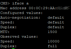
Use the following command to create a network interface:

ipv4 <interface> add <address>/<prefix length> <gateway>

Let’s check:

Hostname

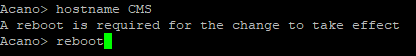
Use the following command to set the hostname:

hostname <name>

Then reboot the system.

The basic configuration is over.

Certificates

Theoretics

Cisco Meeting Server uses an encrypted connection between different components, therefore X.509 certificates are required for all CMS deployments, so servers and services know if they can trust each other.

Each service needs a certificate, but creating a separate certificate for each service may lead to confusion and excessive complexity. Fortunately, we can generate a public and private certificate key pair and then use it for several services. In our case, one and the same certificate will be used for Call Bridge, XMPP server, Web Bridge and Web Admin. So, we only have to create a public/private key pair for each server in a cluster.

Database clustering, however, has special requirements to the certificates, so it needs separate certificates that are different from the other services’ certificates. CMS utilizes a server certificate that is similar to other servers’ certificates, but there also is a client certificate to be used for database connections. Database certificates are used for authentication and encryption both. Instead of providing a username and password to connect a client to the database, it provides a client certificate that is trusted by the server. Each server in a database cluster uses one and the same public/private key pair. So, any server in a cluster can create encrypted data that can be decrypted by any other server that uses the same key pair.

In order for reservation to work properly, a database cluster should consist of three servers at least and five at most, with maximum signal transmission time of 200 ms between any two nodes. This limit is more restrictive than Call Bridge limits, so it usually becomes the limiting factor in geographically distributed deployments.

CMS database role has several specific requirements. Unlike other roles, it requires client and server certificates, with client certificate having the CN field specified to be presented to the server.

CMS uses postgres database with one main server and several identical replications. Every single moment there is only one main database (“database server”). Other nodes are replications or “database clients”.

A database cluster requires a dedicated server certificate and a client certificate. They must be signed, usually by an internal private CA. Since any node in a database cluster can become the main one, the certificates for database server and client (public/private key pairs) must be copied on each server, so it can become a database client or server. Besides that, the root CA certificate must be uploaded, so the client and server certificates can be verified.

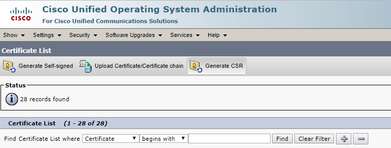
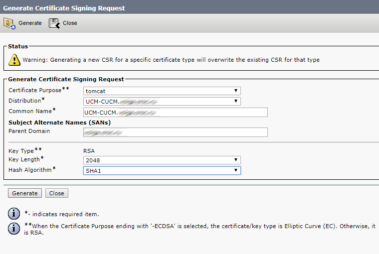
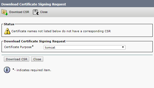
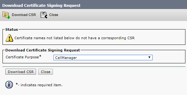
Certificate Requests

So, use the following command to create a certificate request for all server services except database (it will require a separate request):

pki csr hostname CN:cms.example.com
subjectAltName:hostname.example.com,example.com,conf.example.com,join.example.com

CN should contain the common name of our servers. For example, if the hostnames are: server01, server02, server03, the CN should be server.example.com.

Do the same for both other servers with the corresponding hostnames used in commands.

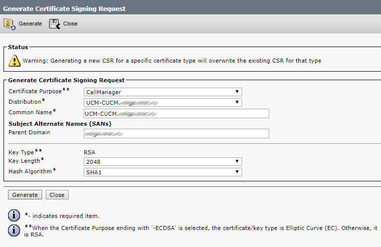
Create two request for the certificates that will be used by the database service:

pki csr dbclusterserver CN:hostname1.example.com
subjectAltName:hostname2.example.com,hostname3.example.com

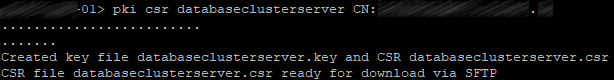
pki csr dbclusterclient CN:postgres

where dbclusterserver and dbclusterclient are the names of our request and future certificates, and hostname1(2)(3) are the corresponding server names.

Perform this procedure on one server only, and upload the certificates and corresponding .key files to the other servers.

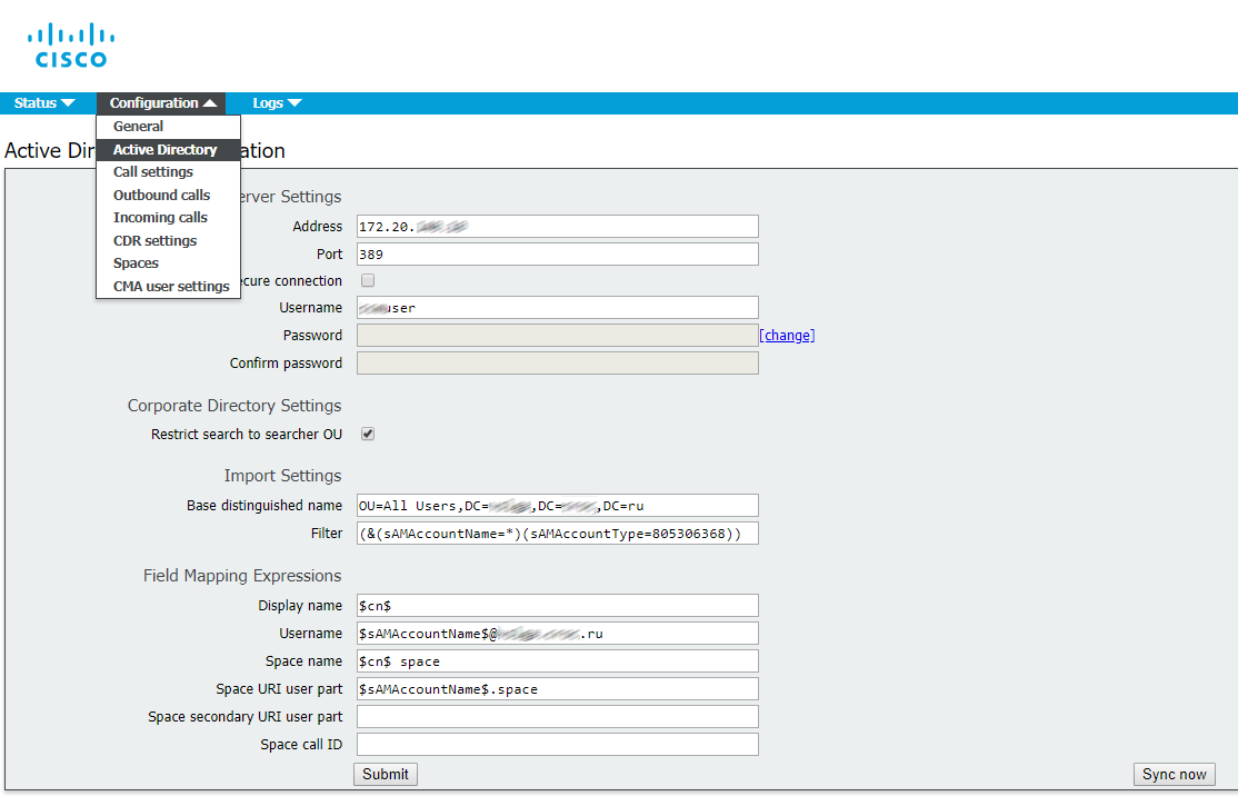
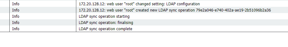
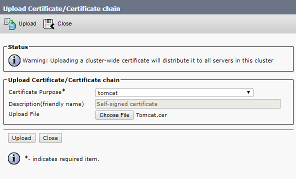
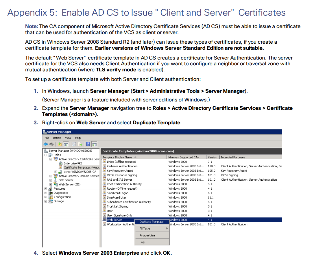
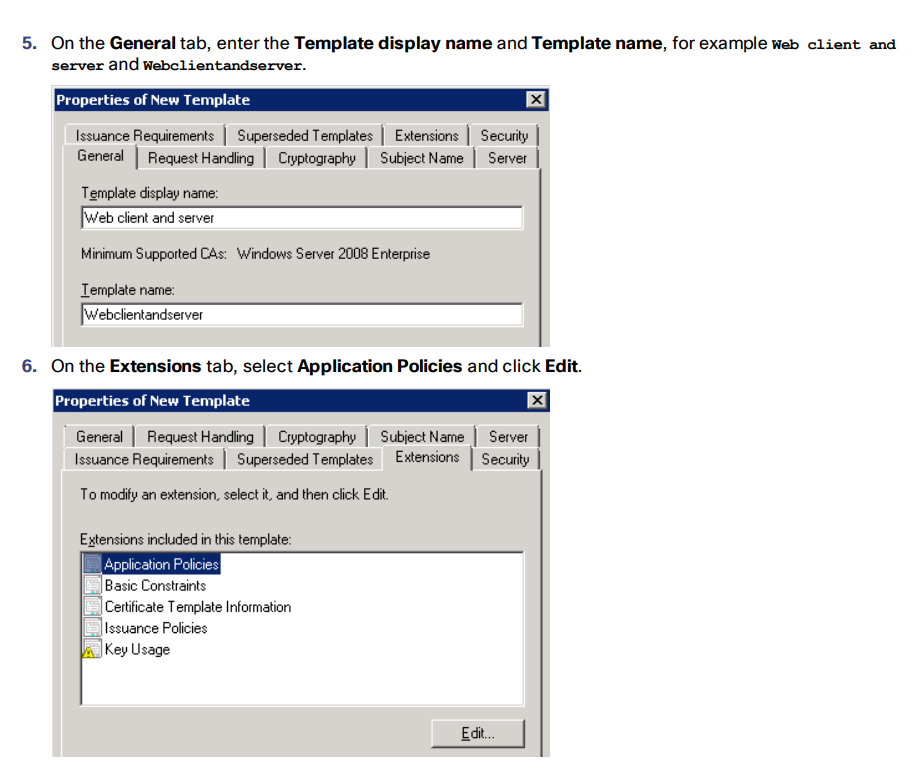
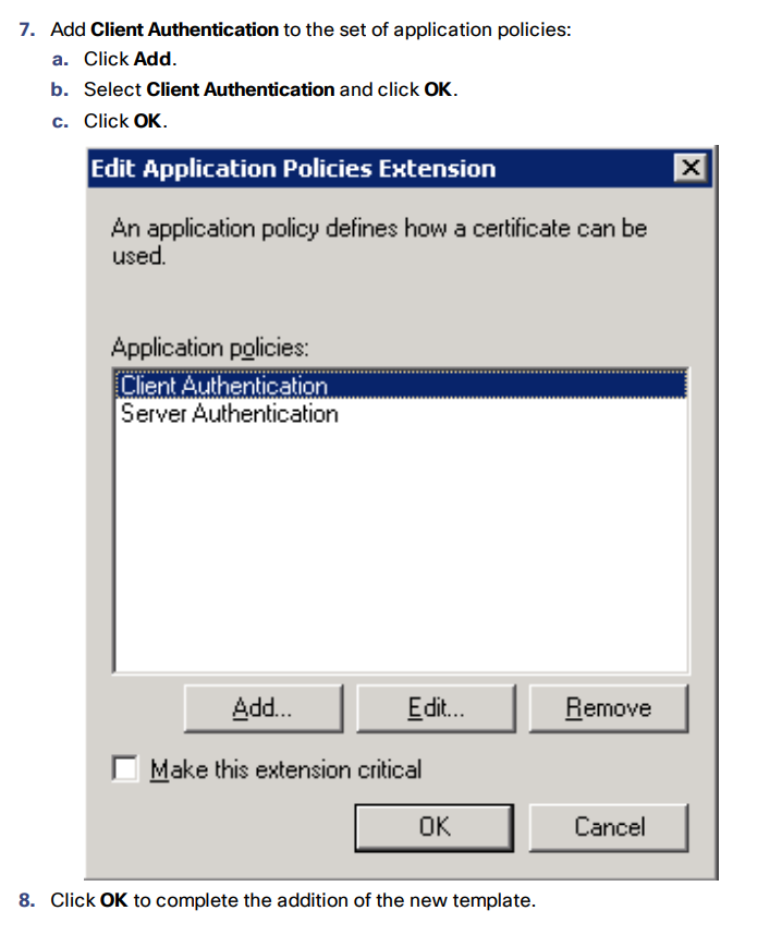
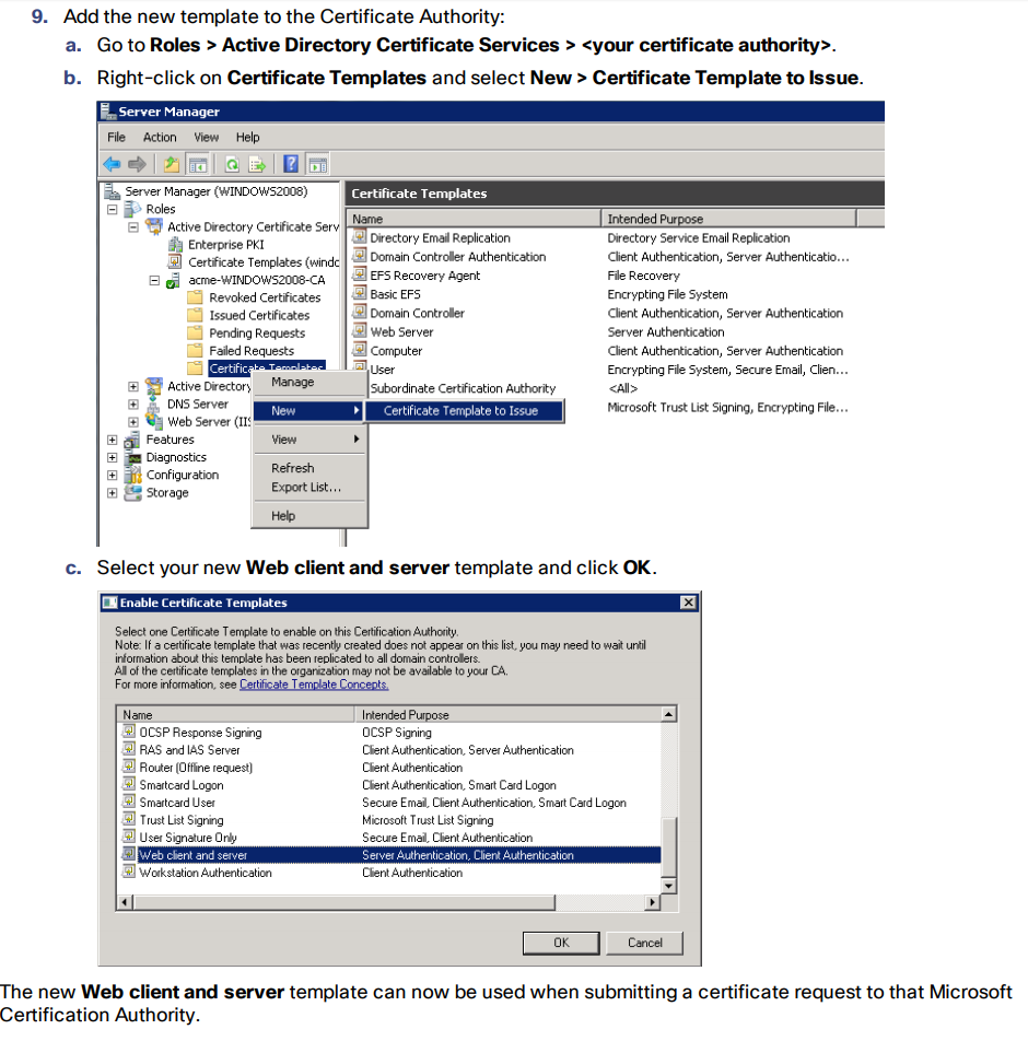
Enable AD CS to Issue “Client and Server” Certificates
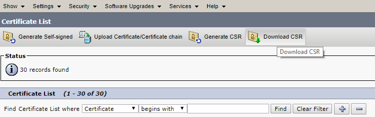
Merge Certificates

Merge all servers’ certificates into one file:

In *NIX:

cat server01.cer server02.cer server03.cer > server.cer

In Windows/DOS:

copy server01.cer + server02.cer + server03.cer server.cer

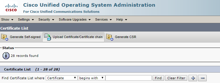
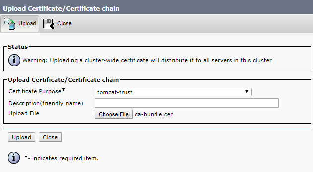
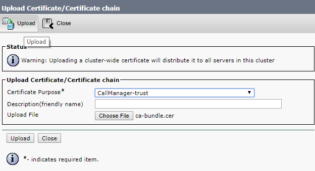
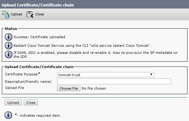
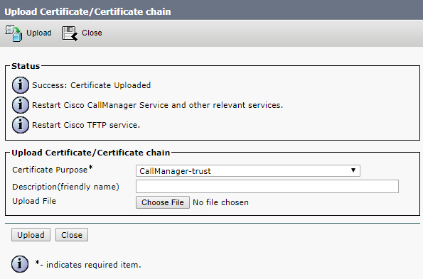
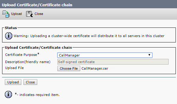
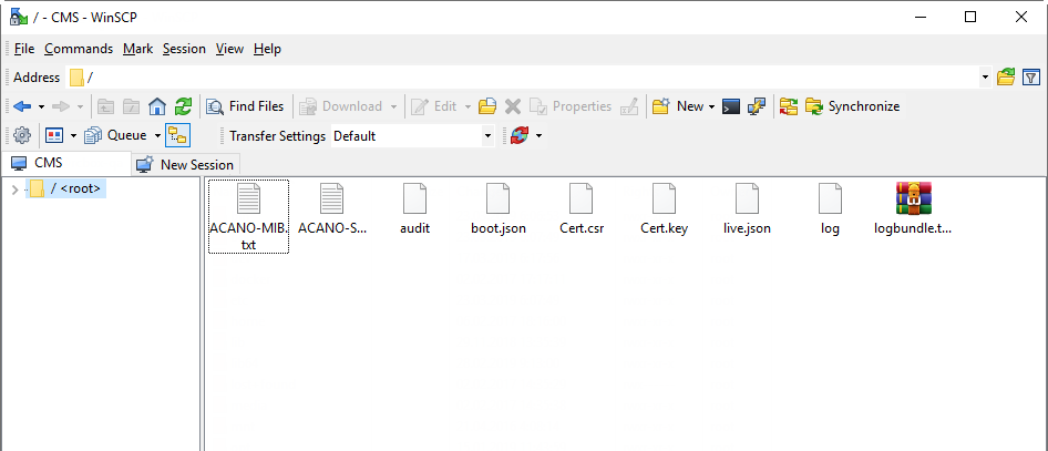
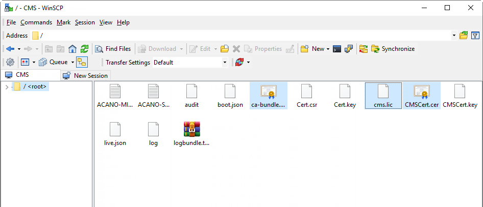
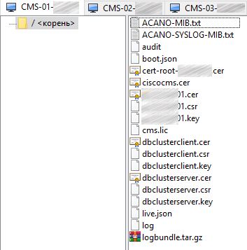
And upload the following files to each server:

  • The server's certificate.
  • Root certificate (with intermediate ones if they exist).
  • Database certificates (“server” and “client” ones) and .key files that have been created upon the request for “server” and “client” database certificates. These are the same files for all servers.
  • All servers’ certificates.

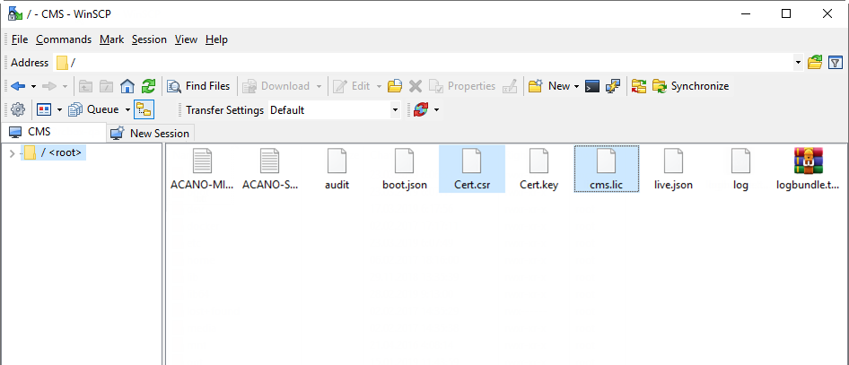
You should get a similar set of files on each server:

In the next part of this article we’ll continue discussing the details of CMS clustered deployment.

Read also:

This article is a translation of a guide originally created by S. Dubinin, Telecommunications Specialist - https://habr.com/ru/post/434240/

CUCM Backup and Recovery via Command Line

Cisco Unified Communications Manager (CUCM) graphic interface has a Disaster Recovery System (DRS) for backup creation and system restore. But sometimes GUI is unavailable, for example, because of network problems. In this case, backup and restore can be performed via CLI. In this article, we’ll tell you how to do that.

Backup Creation

Before this procedure you have to configure a SFTP server to store the CUCM backup there.

First of all, add a server to store the backup. Execute the following command:

utils disaster_recovery device add network [backup_device_name path] [server_name/ip_address] [username] [number_of_backups]

  • backup_device_name – name of the device to store the backup;
  • path – path to the backup on this device;
  • server_name/ip_address – hostname or IP address of the device;
  • username – username to be used to access the server;
  • number of backups – number of backups to be created.

After this command, you’ll be prompted to enter the password for the accessing user (in our case the user is ccmadmin):

admin: utils disaster_recovery device add network backupdevice ./ 10.20.30.123 ccmadmin
Please enter password to connect to network server 10.20.30.123:****
drfCliMsg: Backup Device has been saved successfully.

Use the following command to make sure the backup device has been successfully added:

utils disaster_recovery device list

You should see the device you have added:

admin:utils disaster_recovery device list
Device Name    Device Type    Device Path
--------------------------------------------------------------
backupdevice    NETWORK    ./

Wonderful! Now you can perform the backup. Use the following command:

utils disaster_recovery backup network [featurelist] [path] [backup_device_name] [username]

  • backup_device_name – the hostname or IP address of the device where the backup will be stored;
  • username – username to be used to access the server;
  • featurelist – the list of features for the copy;
  • path – path to the archive.

To show the list of features available for backup, use the following command:

utils disaster_recovery show_registration [servername],

where servername specifies the server for which you want to display the information.

admin:utils disaster_recovery backup network UCM,CDR_CAR,PLM backupdevice
drfCliMsg: Backup initiated successfully. Please run 'utils disaster_recovery status backup' command to see the status

Done! To check the backup status, enter:

utils disaster_recovery status backup

admin:utils disaster_recovery status backup

Status: SUCCESS :Backup Completed...
Tar Filename: 2019-10-12-04-21-37.tar
Storage Location: NETWORK
Operation: backup
Percentage Complete: 100
PLM CCM01 ELM-AGENT SUCCESS Sat Oct 12 04:17:25 CEST 2019 activelog/platform/drf/log/2019-10-12-04-21-37_b_ ccm01_plm_elm-agent.log
PLM CCM01 ELM-SERVER SUCCESS Sat Oct 12 04:17:26 CEST 2019 activelog/platform/drf/log/2019-10-12-04-21-37_b_ ccm01_plm_elm-server.log
CDR_CAR CCM01 CAR SUCCESS Sat Oct 12 04:17:27 CEST 2019 activelog/platform/drf/log/2019-10-12-04-21-37_b_ ccm01_cdr_car_car.log
UCM CCM01 BAT SUCCESS Sat Oct 12 04:19:23 CEST 2019 activelog/platform/drf/log/2019-10-12-04-21-37_b_ ccm01_ucm_bat.log
UCM CCM01 CCMPREFS SUCCESS Sat Oct 12 04:19:25 CEST 2019 activelog/platform/drf/log/2019-10-12-04-21-37_b_ ccm01_ucm_ccmprefs.log
UCM CCM01 PLATFORM SUCCESS Sat Oct 12 04:19:30 CEST 2019 activelog/platform/drf/log/2019-10-12-04-21-37_b_ ccm01_ucm_platform.log
UCM CCM01 TCT SUCCESS Sat Oct 12 04:19:34 CEST 2019 activelog/platform/drf/log/2019-10-12-04-21-37_b_ ccm01_ucm_tct.log
UCM CCM01 SYSLOGAGT SUCCESS Sat Oct 12 04:19:35 CEST 2019 activelog/platform/drf/log/2019-10-12-04-21-37_b_ ccm01_ucm_syslogagt.log
UCM CCM01 CDPAGT SUCCESS Sat Oct 12 04:19:36 CEST 2019 activelog/platform/drf/log/2019-10-12-04-21-37_b_CCM01_ucm_cdpagt.log
UCM CCM01 CLM SUCCESS Sat Oct 12 04:19:37 CEST 2019 activelog/platform/drf/log/2019-10-12-04-21-37_b_ ccm01_ucm_clm.log
UCM CCM01 CCMDB SUCCESS Sat Oct 12 04:19:37 CEST 2019 activelog/platform/drf/log/2019-10-12-04-21-37_b_ ccm01_ucm_ccmdb.log
UCM CCM01 TFTP SUCCESS Sat Oct 12 04:21:37 CEST 2019 activelog/platform/drf/log/2019-10-12-04-21-37_b_ ccm01_ucm_tftp.log
UCM CCM01 ANN SUCCESS Sat Oct 12 04:21:33 CEST 2019 activelog/platform/drf/log/2019-10-12-04-21-37_b_ ccm01_ucm_ann.log
UCM CCM01 MOH SUCCESS Sat Oct 12 04:21:34 CEST 2019 activelog/platform/drf/log/2019-10-12-04-21-37_b_ccm01_ucm_moh.log

That's it, the backup is ready!

Recovery Procedure

To recover CUCM configuration from a backup, first of all, check the backup files available of the remote server:

admin:utils disaster_recovery show_backupfiles backupdevice
2019-10-12-04-21-37
2018-12-25-21-52-19

Select the required backup and enter the following command:

admin:utils disaster_recovery restore network 10.20.30.123 2019-10-12-04-21-37 backupdevice
drfCliMsg: WARNING! There are nodes in current production cluster but NOT present in the backup. These nodes will be removed if you restore the Publisher. If you want to keep these nodes, you will need to manually re-add them after the restore.
Do you want DRS to perform a SHA-1 File Integrity Check of your backup archives y/n ?(n) : y
Please enter the comma seperated features you wish to restore. Valid features for server CCM01 are PLM,CDR_CAR,UCM:PLM,CDR_CAR,UCM
Do you want to restore database from the subscriber y/n ?(n) : n
drfCliMsg: Restore initiated successfully. Please run 'utils disaster_recovery status restore' command to see the status
ALERT: Please restart the server(s) before performing the next restore for changes to take effect. In case of a cluster, restart the entire cluster.

Now check the recovery status:

admin:utils disaster_recovery status restore

Status: SUCCESS :Restore Completed...
Tar Filename: 2019-10-12-04-21-37.tar
Storage Location: NETWORK
Operation: restore
Percentage Complete: 100
CDR_CAR CCM01 CAR SUCCESS Sun Oct 13 11:20:15 CEST 2019 activelog/platform/drf/log/2019-10-12-04-21-37_r_ccm01_cdr_car_car.log
PLM CCM01 ELM-AGENT SUCCESS Sun Oct 13 11:24:34 CEST 2019 activelog/platform/drf/log/2019-10-12-04-21-37_r_ccm01_plm_elm-agent.log
PLM CCM01 ELM-SERVER SUCCESS Sun Oct 13 11:24:34 CEST 2019 activelog/platform/drf/log/2019-10-12-04-21-37_r_ccm01_plm_elm-server.log
UCM CCM01 BAT SUCCESS Sun Oct 13 11:25:06 CEST 2019 activelog/platform/drf/log/2019-10-12-04-21-37_r_ccm01_ucm_bat.log
UCM CCM01 CCMPREFS SUCCESS Sun Oct 13 11:37:06 CEST 2019 activelog/platform/drf/log/2019-10-12-15-20-01_r_ccm01_ucm_ccmprefs.log
UCM CCM01 PLATFORM SUCCESS Sun Oct 13 11:37:13 CEST 2019 activelog/platform/drf/log/2019-10-12-15-20-01_r_ccm01_ucm_platform.log
UCM CCM01 TCT SUCCESS Sun Oct 13 12:11:10 CEST 2019 activelog/platform/drf/log/2019-10-12-15-20-01_r_ccm01_ucm_tct.log
UCM CCM01 SYSLOGAGT SUCCESS Sun Oct 13 12:14:19 CEST 2019 activelog/platform/drf/log/2019-10-12-04-21-37_r_ccm01_ucm_syslogagt.log
UCM CCM01 CDPAGT SUCCESS Sun Oct 13 12:14:39 CEST 2019 activelog/platform/drf/log/2019-10-12-04-21-37_r_ccm01_ucm_cdpagt.log
UCM CCM01 CLM SUCCESS Sun Oct 13 12:17:03 CEST 2019 activelog/platform/drf/log/2019-10-12-04-21-37_r_ccm01_ucm_clm.log
UCM CCM01 CCMDB SUCCESS Sun Oct 13 12:17:05 CEST 2019 activelog/platform/drf/log/2019-02-16-04-21-37_r_ccm01_ucm_ccmdb.log
UCM CCM01 TFTP SUCCESS Sun Oct 13 12:25:12 CEST 2019 activelog/platform/drf/log/2019-02-16-04-21-37_r_ccm01_ucm_tftp.log
UCM CCM01 ANN SUCCESS Sun Oct 13 12:26:38 CEST 2019 activelog/platform/drf/log/2019-02-16-04-21-37_r_ccm01_ucm_ann.log
UCM CCM01 MOH SUCCESS Sun Oct 13 12:26:39 CEST 2019 activelog/platform/drf/log/2019-02-16-04-21-37_r_ccm01_ucm_moh.log

What are you missing in Cisco Meeting Server?

This post is to list some of the gaps of Cisco Meeting Server highlighted by our customers migrating from Cisco TelePresence Server to Meeting Server and partners who deploy Cisco videoconferencing solutions. 


1) UI to configure users and spaces
As you know most of the configuration options are only available via CMS API 

2) Camera snapshots in conference control
The Cisco Meeting Manager tool does not provide camera snapshots. See CMM 2.6 user guide for video operators for more.

3) Monitoring and reporting tool
CMS servers provide API and CDR records but no native reporting tool is available.

4) Lecture mode with hand raising
There used to be a native lecture more for Telepresence Server conferences. Though there are guides about how to configure it with API (see https://kb.acano.com/content/9/68/en/how-do-i-set-up-%E2%80%9Clecture-mode%E2%80%9D.html) the hand raising feature is missing.

5) UI to access meeting recordings
CMS can record meetings (special license is required) but it only stores recording on a NFS. No interface to play recordings, manage access rights etc.

6) Ad-hoc meetings with automatic dial-out
Lots of clients want to start a meeting with a push of a button and have a predefined list of participants to be dialed and joined automatically.

7) Streaming Server
CMS meetings can be streamed to a predefined IP, but you have to deploy some 3rd party media streaming engine to capture it and broadcast to users.

If you feel something major is missing in this list, please give us a shout.

Integration of Cisco Meeting Server with CUCM 11 – PART 3


The last part is about SIP trunking, сonference bridge, route patterns and users.

SIP trunk security profile

Now create a SIP trunk security profile.

If the calls won’t be encrypted, select the values specified below. Enter Call Bridge certificate CN (your CMS server FQDN).

Check Accept Replaces Header if you are going to use conference call bridges.

Conference Bridge

Create a Conference Bridge as described below. Enter username and password of the user with appadmin role (we have created this user in the very beginning).

Create a Media Resource Group and add your Conference Bridge there.

Create Media Resource Group List and add your Media Resource Group there.

Proceed to Standard SIP Profile For TelePresence Conferencing and make sure that Allow iX Application Media, Use Fully Qualified Domain Name in SIP Requests, and Allow Presentation Sharing use BFCP options are checked.

SIP Trunk

Now create a SIP Trunk to CMS server.

You should set the correct Calling Search Space, so calls will be successful. Otherwise, CMS won’t be able to find the required phone number. Both the device and the phone number have to be added to the Calling Search Space.

Media Resource Group List — select the one you have created.

SRTP Allowed flag allows encrypted calls. You can disable it.

SIP Information > Destination address — enter your CMS FQDN or IP address.
SIP Information > Destination Port — standard SIP port is 5060, 5061 is for encrypted calls.
SIP Trunk Security Profile — select the one you have created.
SIP Profile — select Standard SIP Profile For TelePresence Conferencing
Normalization Script — don’t set. It is only needed for encrypted calls. Set cisco-telepresence-conductor-interop if you are using encryption.

Pay attention to the green marked parameters. You should gain an understanding of Calling Search Spaces to fill them correctly.

Leave other fields with default values.

SIP Route Pattern

Create a SIP Route Pattern for calls to SIP addresses like smith.j@example.com

Check CMS and CUCM:

The trunk is up.

However, the Conference Bridge is down due to the difference in TLS versions on CUCM and CMS. This issue can be solved by TLS 1.0 installation on CMS:

tls webadmin min-tls-version 1.0
webadmin restart

Check the Conference Bridge:

Our configuration is being performed on trunks without Media Termination Point (MTP).
Disable MTP if it won’t affect your services.

Disbling MTP can affect your services if your phones use SCCP protocol and you have to send DTMS to CMS.

If this is true for your services, you may have to increase MTP capacity on CUCM depending on the number of simultaneous calls.

Importing Active Directory Users

Now import the users from Active Directory.

Proceed to Configuration -> Active Directory, fill out the fields (see the figure below).

Filter is a very important field. You can enter your own filter or use the filter shown on the picture.

Look through the logs.

Everything is right.

Proceed to Status -> Users to make sure that all users have been imported.

Availability check

We got to the best part.

To perform a call, access the web interface: cms.example.com
Enter an Active Directory user login and password to log in.

Now let’s check a video call from an IP Phone (we are using Cisco E20) to our user account.

I have web and desktop Cisco Meeting clients running, and both are calling.

You can also test the video call from your user account to IP Phone. In our case, the video call was successful in both directions.

Encrypted calls can bring in some complications, but that’s a story for another day.

See also:

Read also:

This article is a translation of a guide originally created by S. Dubinin, Telecommunications Specialist - https://habr.com/ru/post/433528/

Integration of Cisco Meeting Server with CUCM 11 – PART 2


Part 2 explains call settings, Incoming and Outbound calls configuration, spaces and CUCM certificates

Basic Call Settings Configuration

Proceed to Configuration > Call settings and set the values as given below:

Incoming Call Handling Configuration

Proceed to Configuration > Incoming calls and set the values as specified below:

This configuration determines the way of incoming SIP calls handling on CMS. Any call routed to CMS will have a verified alias. The rules in call matching table determine where CMS will look for potential matches. Each rule can be set to match any combination of users, IVR or MicrosoftSkype / Lync. To handle incoming calls, Cisco Meeting Server tries to match the value after "@" sign with the values in “domain name” column.

Outbound Call Handling Configuration

Proceed to Configuration > Outbound calls.
Domain name: leave empty (to match all domains)
SIP Proxy to use: enter your CUCM FQDN (IP address is admissible, but FQDN is recommended)
Local contact domain: leave empty, it is only needed for Skype for Business SIP Trunk configuration.
Local from domain: enter Cisco Meeting Server SIP domain (e.g. cms.example.com)
Trunk type: Standard SIP
Behavior: Continue
Priority: 1
Encryption: Auto or Unencrypted
Click Add New to save the changes.

Space Creation

Create a space where the users will be stored.

Proceed to Configuration > Spaces

The Secondary URI should be a E.164 value compatible with your dial plan that will be routed to CMS. The CallID can be any number that is not used yet. In this example we use the same value as for Secondary URI.

Configure Web Bridge for Call Bridge

To allow guest access to Web Bridge, configure Call Bridge to set Web Bridge address.

Proceed to Configuration > General

Configure a HTTPS CMS URL address for a guest account. For example:
meetingserver.example.com

Fill External Access field if you want to add Cisco Expressway web proxy. This address will be used in invites for external users.

CUCM Certificates

Perform the requests for Tomcat (CUCM web server) and CallManager services.
Proceed to Cisco Unified OS Administration > Security-Certificate Management and click Generate CSR.

First, select Tomcat in the Certificate Purpose field, so you won’t get errors in your browser.

Click Generate.

Then select CallManager, so CMS and CUCM will check each other’s certificates for Conference Bridge registration.

Click Generate.

Now download the certificate signing request files for CA.


Upload root and intermediate certificates for Tomcat-trust and CallManager-trust, either one by one (root certificate first) or as a single file (as described above).

Click Upload.

Upload the CA certificate files formed upon your request.

Now restart Cisco Tomcat, Cisco CallManager and Cisco TFTP services.

Restart Cisco Tomcat from the command line.

The other ones can be restarted from web interface.


Click Restart and wait for the services to be restarted.

Read also:

This article is a translation of a guide originally created by S. Dubinin, Telecommunications Specialist - https://habr.com/ru/post/433528/

Integration of Cisco Meeting Server with CUCM 11 – PART 1


The first part covers network settings, CMS License and Certificates, Call Bridge, Web admin, XMPP, Web Bridge.

This article is about CMS (Cisco Meeting Server) and its integration with CUCM (Cisco Unified Communications Manager).

Suppose that CMS and CUCM have already been deployed on virtual machines.

Before the configuration, make the following preparations:

  • Create a DNS record for CMS IP address with an alias to be used by end users. For example:
    meetingserver.example.com
  • XMPP Domain Name: the name that will be used to log in to Cisco Meeting App. In our case, it will be the user’s sAMAccountName, imported from Active Directory.
  • To support Cisco Meeting App users, add a DNS SRV record for XMPP domain name. SRV record for _xmpp-client._tcp.<xmpp domain> needs TCP port 5222.
  • Note: you don’t need this if you use the desktop application only.
    SIP domain for the meeting server.

Suppose you are using a sub-domen, for example, meet.example.com.

IP address, mask, gateway, DNS, NTP, new user

First of all, enter the valid IP address of your service (CMS has several interfaces, select the first one: "a";).

Add DNS addresses for your zone (if needed). Use "dns" command to check the configuration.

Set CMS hostname and reboot.

It’s recommended to create separate administrator accounts for safety purposes. «Admin» account is not safe enough. Besides that, it’s recommended to have 2 administrator accounts in case you lose one of the administrator passwords. In this situation, you’ll still be able to log in as the second administrator and reset the lost password.

Username: «root», role: «admin».

Getting ahead of it, create another user with role "appadmin", so CUCM will be able to configure CMS on application level via Web Admin interface (i.e. for Conference Bridge registration).

Now set your NTP server and timezone and reboot.

CMS License and Certificates

Now you have to form a request for CMS certificates.

Cisco Meeting Server services use x.509 certificates for TLS connections and for some authentication purposes. In our case, the certificate is needed for Call Bridge, XMPP, Web Bridge and Web Admin services. Certificates can be self-signed or signed by internal or external CA.

Self-signed certificate is admissible, but not recommended, as it causes errors on web pages and prevents registering CMS Conference Bridge on CUCM.

Generate a request:

pki csr Cert CN:example.com subjectAltName:callbridge.example.com,xmpp.example.com,webbridge.example.com

Since we are using one certificate for all services, AltName should contain this services’ names.

Download, install and run WinSCP to get your request file and to put the license file on your CMS server.

To get the license (a 90-days demo version), apply to some Cisco partner and piteously ask for a demo license for education or demonstration purposes, or buy a full license and add your interface MAC address to your piteous letter.

Get the MAC address with the following command: "iface a"

Suppose you get lucky and obtain the license file with .lic extension. Rename it to "cms.lic"

Now run WinSCP. Create a connection to CMS.

Connect:

Save cms.lic and Cert.csr to CMS.

To create a full chain certificate file (because our CMS won’t use .p7b file), do the following:

In a command line:

a. In UNIX OS: cat “intermediate certificate 1” “intermediate certificate 2” “intermediate certificate 3” “root certificate” > ca-bundle

b. In Windows/DOS: copy “intermediate certificate 1” + “intermediate certificate 2” + “intermediate certificate 3” + “root certificate” ca-bundle

Use WinSCP to load the resultant file and the CMS certificate file to CMS.

Reboot, check the license:

Call Bridge, Web admin, XMPP, Web Bridge

Call Bridge

Configure Call Bridge to listen on a interface:

callbridge listen a

Configure Call Bridge to use the certificate, key and CA bundle files:

callbridge certs <keyfile> <certificatefile> <ca bundle>

Restart callbridge:

callbridge restart

Web Admin

Setup Web Admin service:

webadmin listen a 445

Port 445 has been chosen because 443 is already used for web access.
Configure the certificate files for Web Admin service:

webadmin certs <keyfile> <certificatefile> <ca bundle>

And turn it on:

webadmin enable

If everything is right, you'll get SUCCESS messages telling about Web Admin certificate and network parameters being correctly configured. To check if the service is available, enter the web administrator address in your web browser, for example: cms.example.com:445

XMPP

Setup XMPP service:

xmpp listen a

Configure the certificate files for XMPP service:

xmpp certs <keyfile> <certificatefile> <ca bundle>

Set XMPP deployment domain:

xmpp domain <domain name>

Turn the service on:

xmpp enable

Check CMS and CUCM:

Add Call Bridge to XMPP server:

xmpp callbridge add

Copy the Secret and paste it to XMPP server settings, configure the other parameters (see the figure below)

Web Bridge

Setup Web Bridge service:

webbridge listen a:443

Configure the certificate files for Web Bridge service:

webbridge certs <keyfile> <certificatefile> <ca bundle>>

Web Bridge supports HTTPS. If it is configured to use httpredirect, then HTTP will be redirected to HTTPS. To enable HTTP redirection, use the following command:

webbridge http-redirect enable

Use the following command to make Web Bridge trust Call Bridge connections with the certificate previously issued by a certification center:

webbridge trust <certfile>

Read also:

This article is a translation of a guide originally created by S. Dubinin, Telecommunications Specialist - https://habr.com/ru/post/433528/

Is Cisco going to discontinue all its software communication tools except Webex Teams?

1. Cisco Jabber transforms to Teams.

With Cisco Jabber 12.7 release Cisco announced the "Modern Design view" which mirrors the look and feel of Webex Teams user interface.

They say the strategy is to unify its collaboration portfolio to simplify the experience for users and IT administrators.

Ok, but at the same time...

2. Webex Teams App is now available for on-prem deployments with Cisco UCM

The new "Calling in Webex Teams" solution lets you register Webex Teams to the on-prem Cisco UCM (Enterprise, BE 6000/7000, or HCS partner solution).

Here are the details - https://www.cisco.com/c/en/us/td/docs/voice_ip_comm/cloudCollaboration/wbxt/ucmcalling/unified-cm-wbx-teams-deployment-guide/unified-cm-wbx-teams-deployment-guide_chapter_01.html

Will it just replace Cisco Jabber in couple of years?

3. Webex Teams and Webex Meetings are getting merged

Until recently Webex Teams and Webex Meetings were separate products relying on different cloud platforms.

Now Cisco brings them closer together - https://searchunifiedcommunications.techtarget.com/news/252465007/Cisco-unifies-Webex-calling-messaging-and-meetings

4. Cisco IP communicator, my love, reaches its end of life

And even more... The end-of-sale and end-of-life dates are announced for Cisco IP Communicator.

5. Is Cisco Meeting App next?

Now rumors are that Cisco Meeting App which is the software endpoint for Cisco Meeting Server is also going away soon.

If this is really going to happen, guess what will the replacement be?

CUCM SIP CUBE: Manipulations with INVITE Field

Some SIP providers prefer to work with INVITE field, while CISCO CUBE traditionally works with From: and To: fields.

Let’s take MSN provider as an example.

An incoming call header looks like this:

In this case, login is 48879800, and it is contained in INVITE field only.

Cisco translation-profile and translation-rule can only operate with numbers, and the complex header in To: field complicates the situation.

You can use sip-profiles to copy the number from INVITE field to To: field.

The structure should be the following:

voice service voip
  sip
    sip-profiles inbound
!
voice class sip-profiles 10
    request INVITE sip-header SIP-Req-URI copy "sip:(.*)@" u01
    request INVITE sip-header To modify ".*@(.*)" "To: voice translation-rule 10
  rule 1 /^48879800$/ /1401/
!
voice translation-rule 20
  rule 1 /^8\(..........$\)/ /+7\1/
!
!
voice translation-profile ITSP_Incoming
  translate calling 20
  translate called 10
!
dial-peer voice 1 voip
  description incoming from MCN-1
  translation-profile incoming ITSP_Incoming
  session protocol sipv2
  session target sip-server
  incoming called-number 48879800
  voice-class codec 1
  voice-class sip profiles 10 inbound
  voice-class sip bind control source-interface GigabitEthernet0/0/0.300
  voice-class sip bind media source-interface GigabitEthernet0/0/0.300
  dtmf-relay rtp-nte digit-drop
  no vad
!
dial-peer voice 500115 voip
  description To CUCM
  preference 5
  destination-pattern 48879800
  session protocol sipv2
  session target ipv4:10.7.20.251
  voice-class codec 1
  voice-class sip bind control source-interface GigabitEthernet0/0/1.200
  voice-class sip bind media source-interface GigabitEthernet0/0/1.200
  dtmf-relay rtp-nte digit-drop
  ip qos dscp cs3 signaling
  no vad
!

Then the number 48879800 can be sent to CUCM.

In the end, the call will look like this:

CUCM DRS Management Using Command Line

Command Line Recovery

Hello! In a recent article we have shown you how to create a backup for Cisco Unified Communications Manager (CUCM) using Disaster Recovery System (DRS). Today we'll discuss backup and recovery in command line interface (CLI) that can be used when it’s impossible to use graphical interface.

Backup Creation

First of all, select the device to store the backup (SFTP server). Execute the following command:

utils disaster_recovery device add network [devicename path] [server_name/ip_address] [username] [number_of_backups]

  • devicename – name of the device to store the backup;
  • path – path to the backup;
  • server_name/ip_address – hostname or IP address of the device where the backup will be stored;
  • username – username to be used to access the server;
  • number_of_backups – number of backups to be created (optional). The default value is 2;

Example:

admin: utils disaster_recovery device add network networkDevice /root 192.168.1.1 root 3

The following command shows the list of devices:

utils disaster_recovery device list

Now create a backup copy:

utils disaster_recovery backup network [featurelist] [path] [servername] [username]

  • featurelist – the list of features for the copy, separated by comma;
  • path – path to the archive;
  • servername – the hostname or IP address of the device where the archive will be stored;
  • username – username to be used to access the server;

The following command shows the feature list:

utils disaster_recovery show_registration

Check the backup status:

utils disaster_recovery status backup

Recovery

First of all, check whether there are backup files on SFTP server:

utils disaster_recovery show_backupfiles [name]

  • name – the name of backup device;

Select a backup file from the list:

utils disaster_recovery restore network [restore_server] [tarfilename] [devicename]

  • restore_server – the hostname or IP address of the device where the archive will be stored;
  • tarfilename – backup file name;
  • devicename – the name of backup device;

Example:

utils disaster_recovery restore network 192.168.1.1 2019-05-15-15-35-28 networkDevice

When asked if you really want to restore the system, say “y”.

Now check the system recovery status:

utils disaster_recovery status restore

Integrating Cisco UCCX with a Database Using a Script

If you have UCCX (Cisco Unified Contact Center Express) premium license, one of the best features is possible integration and requests to database. These requests can use any information provided by the caller, or the caller’s number, etc.

It’s very important to create a reasonable initial script design and to take the server load into account. Big and heavy scripts with many database handles increase the load greatly. If the DB is on a remote server and there is a net lag, it may influence your business and the calling client's loyalty.

CISCO UNIFIED CCX SCRIPT EDITOR Review

There is a special tool in UCCX to create and manage IVR scripts: Cisco Unified CCX Editor. Here you can manage visual blocks responsible for this or that action. It looks like this:

Let’s look at the Database section. It has 4 items:

  • DB Get – map the data from DB to the script variables;
  • DB Read – connect to the server and send a request;
  • DB Release – close the connection with DB;
  • DB Write – use Write method if changes in DB are required;

On the screenshot above, you can see that each script begins with Start event and ends with End event. As the script is being executed during a call, we can perform as many DB requests as we need. Each request has its own sequence of steps that are listed above.

We recommend you to test all SQL requests, access to the system and other factors before releasing to the enterprise environment.

As an example, let's look into DB Read block:

These fields are available for configuration:

  • DB Resource Name – marker of the request;
  • Data Source Name – data source specified in UCCX console (Cisco Unified CCX Administration Database);
  • Timeout (in sec) – request execution timeout. This timeout protects your system from database disconnection. If you set it to 0, the request won’t have any time limitations;

Now proceed from General tab to Field Selection:

  • Write the SQL request you want to execute. For example: SELECT fld1, fld2 from tbl where fld1 = $variable – select two fields from the table, where the first field’s value is equal to a variable that we have initialized earlier in our script.
  • Test (button) – click this button to check the request syntax and the database connection;
  • Number of rows returned – number or rows returned by the request after the Test button was clicked;
  • Show all fields (select table/view) – show all fields of the used tables;

Now let’s look into DB Get block:

  • DB Resource Name – label or name of this request;
  • Data Source Name – database name (configured in Cisco Unified CCX Administration panel);
  • Refresh Database Schema (button) – click this button to load database data and tables to CCX Editor;

Proceed to Field Selection tab:

  • Table/View – name of the DB table that was selected on General tab (see above);
  • Table fields:
  • Field Name – field name in the selected table;
  • Data Type – data type (string/number, etc.);
  • Local Variable – script variable that will store the corresponding field value;
  • Add/Modify (buttons) – buttons responsible for field modification (except for data type, which is read-only);

The obtained data can be used in the script, for example, to vocalize (using TTS) the client’s phone number or the entered digits (e.g. order number).

Deprecated Cisco IP Phones in CUCM 14

Remember this mess with several tens of Cisco IP phones available on the market (not counting video endpoints)?
There were:

  • old-school 7900 series,
  • intermediate 6900, 8900 and 9900 models,
  • newly introduced 7800 and 8800 IP phones,
  • finally some experiments like 3905, Android-based DX650 etc

So these times are over.

For the past couple of year Cisco step by step cleaned up the IP phones portfolio: In Cisco Unified Communications Manager 11.5 they deprecated 7902, 7905, 7910, 7912, 7920, Conference Station 7935.
The following models were deprecated in Cisco UCM 12 - wireless IP Phone 7921, 7970 and 7971.

And now the MAJOR CLEANUP is coming with Cisco Unified Communications Manager, Release 14 affecting CUCM 14, Cisco BE 6000 / 7000.

Just take a look. The phone models to be deprecated in Release 14 are:
- Cisco Unified SIP Phone 3911
- Cisco Unified SIP Phone 3951
- Cisco Unified IP Phone 6911
- Cisco Unified IP Phone 6921
- Cisco Unified IP Phone 6941
- Cisco Unified IP Phone 6945
- Cisco Unified IP Phone 6961
- Cisco Unified IP Phone 7906G
- Cisco Unified IP Phone 7911G
- Cisco Unified Wireless IP Phone 7925
- Cisco Unified Wireless IP Phone 7925G-EX
- Cisco Unified Wireless IP Phone 7926
- Cisco Unified IP Phone 7931
- Cisco Unified IP Conference Station 7936
- Cisco Unified IP Conference Station 7937G
- Cisco Unified IP Phone 7940
- Cisco Unified IP Phone 7941
- Cisco Unified IP Phone 7960
- Cisco Unified IP Phone 7961
- Cisco Unified IP Phone 7985
- Cisco Unified IP Phone 8941

If you are using any of these phone models and you upgrade to Release 14, you will not be able to use these phones after the upgrade.

After you switch over to CUCM 14, registration of these phone models will be blocked.

So, better check the phones you use and plan the migration to 7800 and 8800 series in advance.

Field notice from Cisco - https://www.cisco.com/c/en/us/td/docs/voice_ip_comm/cucm/trouble/14_0_1/fieldNotices/cucm_b_deprecated-phones-14.html

Enabling Cisco UCM CDR Collection

Yes, CUCM can collect CDR (Call Detail Record). This article will show you how to enable this feature (disabled by default).

Enabling CDR

Open Cisco Unified CM Administration interface:

Proceed to System → Service Parameters and select the following parameters:

  • Server — select the node to be manipulated,
  • Service — select Cisco CallManager (Active).

In the Parameters section that appears, find System and select:

  • CDR Enabled Flag * — True. This parameter indicates the call manager to create and store CDR records for each call passing through this UCM;
  • CDR Log Calls with Zero Duration Flag * — True. Enabling this parameter makes the server save the unsuccessful calls and calls that were shorter than 1 second (helpful for troubleshooting).

Don’t forget to apply the changes. Repeat this actions for each node in a cluster (if you have more than one server in System → Service Parameters → Server menu).

Additional configuration

Now let’s explore advanced parameters. On the configuration toolbar, click Advanced:

Select the following options:

  • Call Diagnostics Enabled – Enabled Only When CDR Enabled Flag is True. This parameter switches on so-called Call Management Records (CMR), which are very helpful for troubleshooting;
  • Display FAC in CDR – True. This parameter indicates whether Forced Authorization Code (FAC) should be displayed in CDR. Generally, this parameter depends on your security policies. We chose to display it;
  • Show Line Group Member DN in finalCalledPartyNumber CDR Field – True. Briefly, this parameter shows DN (directory number) of the group member that answered a call, instead of the group’s number;
  • Show Line Group Member Non Masked DN in finalCalledPartyNumber CDR Field – basically, the same as the previous one.

Open Cisco Unified Serviceability page, proceed to Tools → CDR Analysis and Reporting section. Now you can select CDR tab to use Search or export the data. Enjoy!