 This article presents a small set of commands for Cisco Voice Operation System (VOS) based servers. These commands help to reveal most problems caused by the platform. Each command comes with a brief description. The most important output data is marked with bold.
1. show status
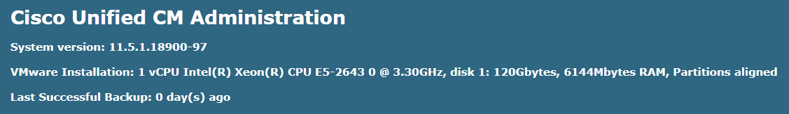
If you need to analyse any problem, this is the first command to begin with. It displays the server’s name, its version and uptime. Since Cisco VOS servers are built on the basis of Linux Red Hat (RH), it may be handy to know your RH version, which in this case is 6.0. Average processor load above 60-70%, IOWAI above 1-2% and disk usage above 95% for any partition may indicate potential problems with this server.
admin:show status
Host Name : ucm11-1
Date : Mon Feb 13, 2017 22:24:14
Time Zone : Central European Time (Europe/Warsaw)
Locale : en_US.UTF-8
Product Ver : 11.0.1.20000-2
Unified OS Version : 6.0.0.0-2
Uptime:
22:24:19 up 20 days, 10:34, 1 user, load average: 0.27, 0.16, 0.13
CPU Idle: 94.94% System: 02.78% User: 02.28%
IOWAIT: 00.00% IRQ: 00.00% Soft: 00.00%
Memory Total: 8062356K
Free: 147272K
Used: 7915084K
Cached: 3739040K
Shared: 451788K
Buffers: 288744K
Total Free Used
Disk/active 20173692K 7107128K 12860280K (65%)
Disk/inactive 20173692K 7443172K 12524236K (63%)
Disk/logging 70515112K 21109572K 45816884K (69%)
2. show tech network hosts
This command can be used to get the list of servers in a cluster in a convenient format. The main purpose is to understand the scale of a system: 1 server means no fault tolerance, 8 servers mean that the system serves a lot of users and any changes must be carefully thought out and coordinated with the customer. The output of this command must be the same for all the servers in your cluster. Otherwise, there may be problems with database replication.
admin:show tech network hosts
——————– show platform network ——————–
/etc/hosts File:
#This file was generated by the /etc/hosts cluster manager.
#It is automatically updated as nodes are added, changed, removed from the cluster.
127.0.0.1 localhost
::1 localhost
10.48.47.136 ucm11-2.allevich.local ucm11-2
10.48.47.143 ucm11-1.allevich.local ucm11-1
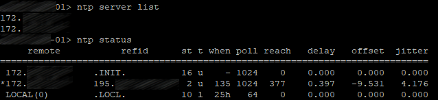
3. utils ntp status
Synchronization with an NTP server is mandatory for all the devices in your network. Timestamps help with malfunction diagnostics, especially in complicated cases. Informix DB replication won’t be stable without NTP synchronization. This command can also be used to indicate the date and time when the commands in a saved text file were executed.
admin:utils ntp status
ntpd (pid 8524) is running…
remote refid st t when poll reach delay offset jitter
==============================================================================
*172.18.108.15 .GPS. 1 u 583 1024 377 106.518 0.283 1.045
synchronised to NTP server (172.18.108.15) at stratum 2
time correct to within 131 ms
polling server every 1024 s
Current time in UTC is : Mon Feb 13 21:24:23 UTC 2017
Current time in Europe/Warsaw is : Mon Feb 13 22:24:23 CET 2017
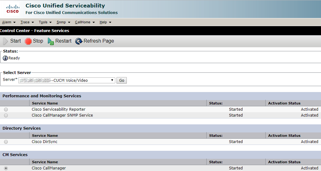
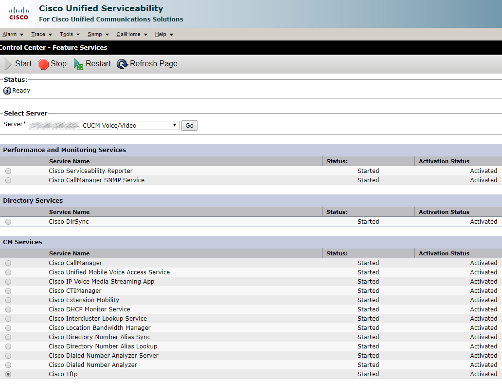
4. utils service list
This command is necessary if you need to check the state of all services running on a certain server in a cluster. This is also the simplest way to find the Publisher server in a cluster: it will have the directive “primary node=true”.
admin:utils service list
Requesting service status, please wait…
System SSH [STARTED]
Cluster Manager [STARTED]
Name Service Cache [STARTED]
Entropy Monitoring Daemon [STARTED]
Cisco SCSI Watchdog [STARTED]
Service Manager [STARTED]
HTTPS Configuration Download [STARTED]
Service Manager is running
Getting list of all services
>> Return code = 0
A Cisco DB[STARTED]
A Cisco DB Replicator[STARTED]
Cisco AMC Service[STARTED]
Cisco AXL Web Service[STARTED]
Cisco Audit Event Service[STARTED]
Cisco Bulk Provisioning Service[STARTED]
Cisco CAR DB[STARTED]
Cisco CAR Scheduler[STARTED]
Cisco CAR Web Service[STARTED]
Cisco CDP[STARTED]
Cisco CDP Agent[STARTED]
Cisco CDR Agent[STARTED]
Cisco CDR Repository Manager[STARTED]
Cisco CTIManager[STARTED]
Cisco CTL Provider[STARTED]
Cisco CallManager[STARTED]
Cisco CallManager Admin[STARTED]
Cisco CallManager SNMP Service[STARTED]
Cisco CallManager Serviceability[STARTED]
Cisco CallManager Serviceability RTMT[STARTED]
Cisco Certificate Authority Proxy Function[STARTED]
Cisco Certificate Change Notification[STARTED]
Cisco Certificate Expiry Monitor[STARTED]
Cisco Change Credential Application[STARTED]
Cisco DHCP Monitor Service[STARTED]
Cisco DRF Local[STARTED]
Cisco DRF Master[STARTED]
Cisco Database Layer Monitor[STARTED]
Cisco DirSync[STARTED]
Cisco E911[STARTED]
Cisco ELM Client Service[STARTED]
Cisco Extended Functions[STARTED]
Cisco Extension Mobility[STARTED]
Cisco Extension Mobility Application[STARTED]
Cisco IP Manager Assistant[STARTED]
Cisco IP Voice Media Streaming App[STARTED]
Cisco Intercluster Lookup Service[STARTED]
Cisco License Manager[STARTED]
Cisco Log Partition Monitoring Tool[STARTED]
Cisco Prime LM Admin[STARTED]
Cisco Prime LM DB[STARTED]
Cisco Prime LM Server[STARTED]
Cisco RIS Data Collector[STARTED]
Cisco RTMT Reporter Servlet[STARTED]
Cisco SOAP – CDRonDemand Service[STARTED]
Cisco SOAP – CallRecord Service[STARTED]
Cisco Serviceability Reporter[STARTED]
Cisco Syslog Agent[STARTED]
Cisco TAPS Service[STARTED]
Cisco Tftp[STARTED]
Cisco Tomcat[STARTED]
Cisco Tomcat Stats Servlet[STARTED]
Cisco Trace Collection Service[STARTED]
Cisco Trace Collection Servlet[STARTED]
Cisco Trust Verification Service[STARTED]
Cisco UXL Web Service[STARTED]
Cisco Unified Mobile Voice Access Service[STARTED]
Cisco User Data Services[STARTED]
Cisco WebDialer Web Service[STARTED]
Host Resources Agent[STARTED]
MIB2 Agent[STARTED]
Platform Administrative Web Service[STARTED]
SNMP Master Agent[STARTED]
SOAP – Diagnostic Portal Database Service[STARTED]
SOAP -Log Collection APIs[STARTED]
SOAP -Performance Monitoring APIs[STARTED]
SOAP -Real-Time Service APIs[STARTED]
System Application Agent[STARTED]
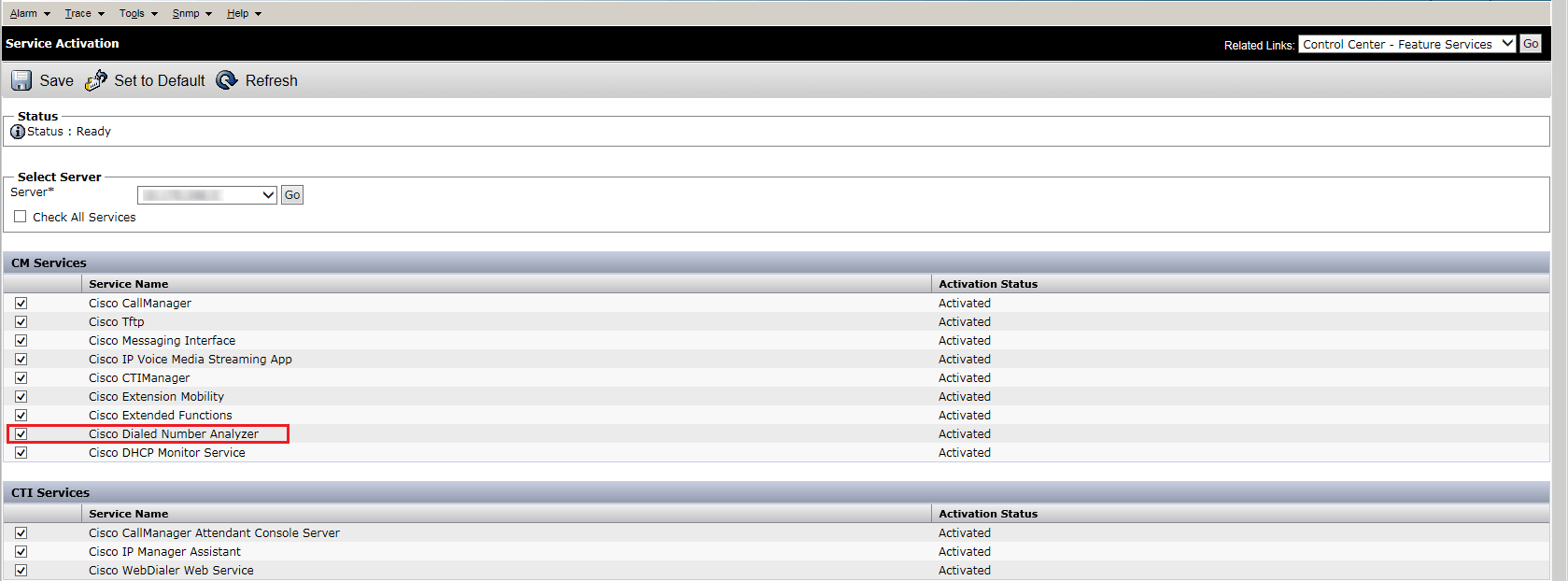
Cisco Dialed Number Analyzer[STOPPED] Service Not Activated
Cisco Dialed Number Analyzer Server[STOPPED] Service Not Activated
Cisco Directory Number Alias Lookup[STOPPED] Service Not Activated
Cisco Directory Number Alias Sync[STOPPED] Service Not Activated
Cisco Location Bandwidth Manager[STOPPED] Service Not Activated
Cisco Prime LM Resource API[STOPPED] Service Not Activated
Cisco Prime LM Resource Legacy API[STOPPED] Service Not Activated
Self Provisioning IVR[STOPPED] Service Not Activated
Primary Node =true
5. utils dbreplication runtimestate
Many problems, especially the ones that are difficult to reproduce, originate from Informix database replication malfunction. To ensure that the replication is working correctly, pay attention to the marked fields. All the tables should be synchronized, basic check-ups should be successful (“Y” status), the status of each node should be equal to 2. Another useful piece of information is the timeout between the nodes in a cluster (in ms). For the servers that are located in different data centers far from each other it is usually above 10 ms.
admin:utils dbreplication runtimestate
Server Time: Mon Feb 13 22:24:51 CET 2017
Cluster Replication State: BROADCAST SYNC ended at: 2016-02-25-08-48
Sync Result: SYNC COMPLETED on 692 tables out of 692
Sync Status: All Tables are in sync
Use CLI to see detail: ‘file view activelog cm/trace/dbl/20160225_084649_dbl_repl_output_Broadcast.log’
DB Version: ccm11_0_1_20000_2
Repltimeout set to: 420s
PROCESS option set to: 1
Cluster Detailed View from ucm11-1 (2 Servers):
PING DB/RPC/ REPL. Replication REPLICATION SETUP
SERVER-NAME IP ADDRESS (msec) DbMon? QUEUE Group ID (RTMT) & Details
———– ———- —— ——- —– ———– ——————
ucm11-2 10.48.47.136 2.860 Y/Y/Y 0 (g_3) (2) Setup Completed
ucm11-1 10.48.47.143 0.038 Y/Y/Y 0 (g_2) (2) Setup Completed
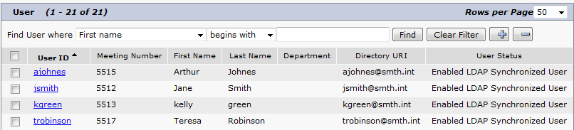
6. run sql SELECT count(*) from enduser
To analyze any problem, a Cisco TAC engineer has to know the number of users in your system. It helps to understand its size and estimate the business impact of this service.
admin:run sql SELECT count(*) from enduser
(count(*))
==========
11
Other VOS-based servers usually store user data in a separate Informix DB.
Commands for other servers (CUIC, Unity Connection) are given below.
run sql SELECT count(*) from cuic_data:cuicuser
run cuc dbquery unitydirdb SELECT count(*) FROM tbl_user
7. utils core active list
Checking memory dumps of the processes is a part of the initial diagnostics. An example of Call Manager process memory dump is given below. Analyzing memory dumps is Cisco TAC engineers’ work, as it requires the knowledge of the product’s software architecture.
admin:utils core active list
Size Date Core File Name
=================================================================
233860 KB 2017-02-02 09:28:40 core.20919.6.ccm.1486023981
8. file dump install system-history.log
This command is irreplaceable for the analysis of any problem. It displays the events that have occurred on a node: restarts, installation of components (COP files, locales), successful and failed backups.
file dump install system-history.log
=======================================
Product Name – Cisco Unified Communications Manager
Product Version – 11.0.1.20000-2
Kernel Image – 2.6.32-504.12.2.el6.x86_64
=======================================
05/18/2015 17:49:21 | root: Install 11.0.0.99833-4 Start
05/18/2015 23:28:40 | root: Boot 11.0.0.99833-4 Start
05/19/2015 09:55:13 | root: Install 11.0.0.99833-4 Success
05/19/2015 09:55:17 | root: Boot 11.0.0.99833-4 Start
06/17/2015 17:51:57 | root: Shutdown 11.0.0.99833-4 Start
06/18/2015 12:37:00 | root: Boot 11.0.0.99833-4 Start
08/16/2015 08:18:19 | root: Boot 11.0.0.99833-4 Start
09/09/2015 08:47:37 | root: Boot 11.0.0.99833-4 Start
12/02/2015 16:18:19 | root: Cisco Option Install cm-locale-de_DE-11.0.1.1000-1.cop Start
12/02/2015 16:20:34 | root: Cisco Option Install cm-locale-de_DE-11.0.1.1000-1.cop Success
12/02/2015 16:22:58 | root: Restart 11.0.0.99833-4 Start
12/02/2015 16:23:32 | root: Boot 11.0.0.99833-4 Start
12/02/2015 16:31:51 | root: Restart 11.0.0.99833-4 Start
12/02/2015 16:32:15 | root: Boot 11.0.0.99833-4 Start
12/08/2015 17:33:35 | root: Shutdown 11.0.0.99833-4 Start
12/08/2015 22:47:20 | root: Boot 11.0.0.99833-4 Start
12/28/2015 21:59:19 | root: Upgrade 11.0.1.20000-2 Start
12/28/2015 22:57:54 | root: Upgrade 11.0.1.20000-2 Success
12/28/2015 22:58:22 | root: Switch Version 11.0.0.99833-4 to 11.0.1.20000-2 Start
12/28/2015 23:01:06 | root: Switch Version 11.0.0.99833-4 to 11.0.1.20000-2 Success
12/28/2015 23:01:06 | root: Product Version 11.0.1.20000-2
12/28/2015 23:01:06 | root: Kernel Image 2.6.32-504.12.2.el6.x86_64
12/28/2015 23:01:09 | root: Restart 11.0.1.20000-2 Start
12/28/2015 23:01:10 | root: Restart 11.0.0.99833-4 Start
12/28/2015 23:03:12 | root: Boot 11.0.1.20000-2 Start
01/31/2016 12:54:02 | root: Cisco Option Install dp-ffr.3-1-30.GB.k3.cop Start
01/31/2016 12:55:11 | root: Cisco Option Install dp-ffr.3-1-30.GB.k3.cop Success
02/07/2016 11:09:46 | root: Cisco Option Install cm-locale-ru_RU-11.0.1.1000-1.cop Start
02/07/2016 11:11:41 | root: Cisco Option Install cm-locale-ru_RU-11.0.1.1000-1.cop Success
02/07/2016 11:37:46 | root: Restart 11.0.1.20000-2 Start
02/07/2016 11:38:19 | root: Boot 11.0.1.20000-2 Start
03/30/2016 12:39:11 | root: Restart 11.0.1.20000-2 Start
03/30/2016 12:39:38 | root: Boot 11.0.1.20000-2 Start
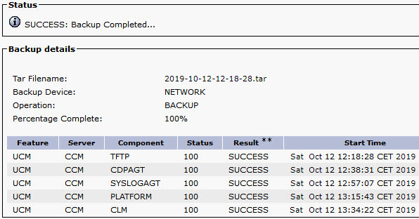
04/16/2016 13:21:04 | root: DRS Backup UCMVersion:11.0.1.20000-2 Start
04/16/2016 13:23:37 | root: DRS Backup UCMVersion:11.0.1.20000-2 Success
04/28/2016 13:59:03 | root: DRS Backup UCMVersion:11.0.1.20000-2 Start
04/28/2016 14:03:06 | root: DRS Backup UCMVersion:11.0.1.20000-2 Success
05/03/2016 11:03:46 | root: Shutdown 11.0.1.20000-2 Start
05/03/2016 11:08:43 | root: Boot 11.0.1.20000-2 Start
05/14/2016 20:10:29 | root: Restart 11.0.1.20000-2 Start
05/14/2016 20:10:57 | root: Boot 11.0.1.20000-2 Start
01/17/2017 12:44:09 | root: Restart 11.0.1.20000-2 Start
01/17/2017 12:44:59 | root: Boot 11.0.1.20000-2 Start
01/22/2017 01:00:05 | root: DRS Backup UCMVersion:11.0.1.20000-2 Start
01/22/2017 01:07:36 | root: DRS Backup UCMVersion:11.0.1.20000-2 Success
01/24/2017 11:49:36 | root: Restart 11.0.1.20000-2 Start
01/24/2017 11:50:14 | root: Boot 11.0.1.20000-2 Start
01/29/2017 01:00:11 | root: DRS Backup UCMVersion:11.0.1.20000-2 Start
01/29/2017 01:21:57 | root: DRS Backup UCMVersion:11.0.1.20000-2 Success
02/05/2017 01:00:05 | root: DRS Backup UCMVersion:11.0.1.20000-2 Start
02/05/2017 01:10:58 | root: DRS Backup UCMVersion:11.0.1.20000-2 Success
02/12/2017 01:00:05 | root: DRS Backup UCMVersion:11.0.1.20000-2 Start
02/12/2017 01:12:51 | root: DRS Backup UCMVersion:11.0.1.20000-2 Success
Even if the data acquired by these commands doesn’t show the problem’s source, it significantly improves the engineer’s knowledge of the system, its current state, version, addresses and services.
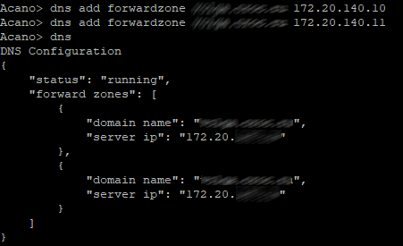
P.S. This list doesn’t include the following command because it may take a long time to produce the output. If the DNS reverse records are not configured correctly, this command will take 300 seconds longer to execute.
utils diagnose test
This article is a translation of a guide originally created by Alex Levichev, a Cisco UC TAC engineer - https://gblogs.cisco.com/ru/author/allevich/


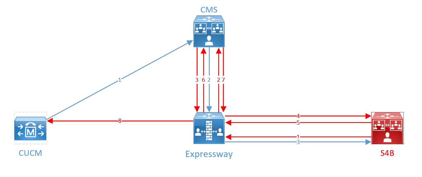


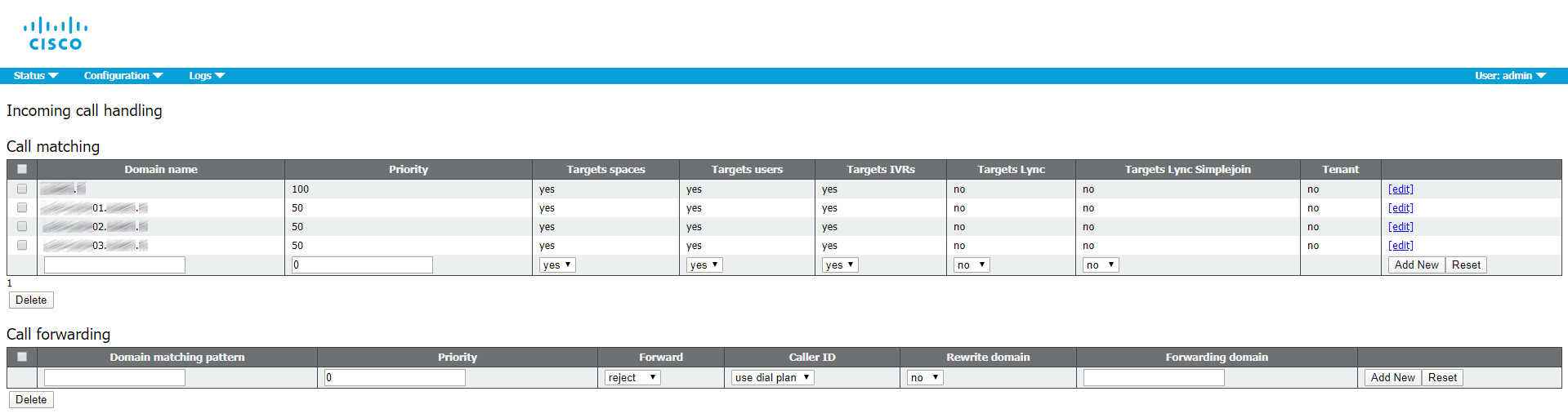


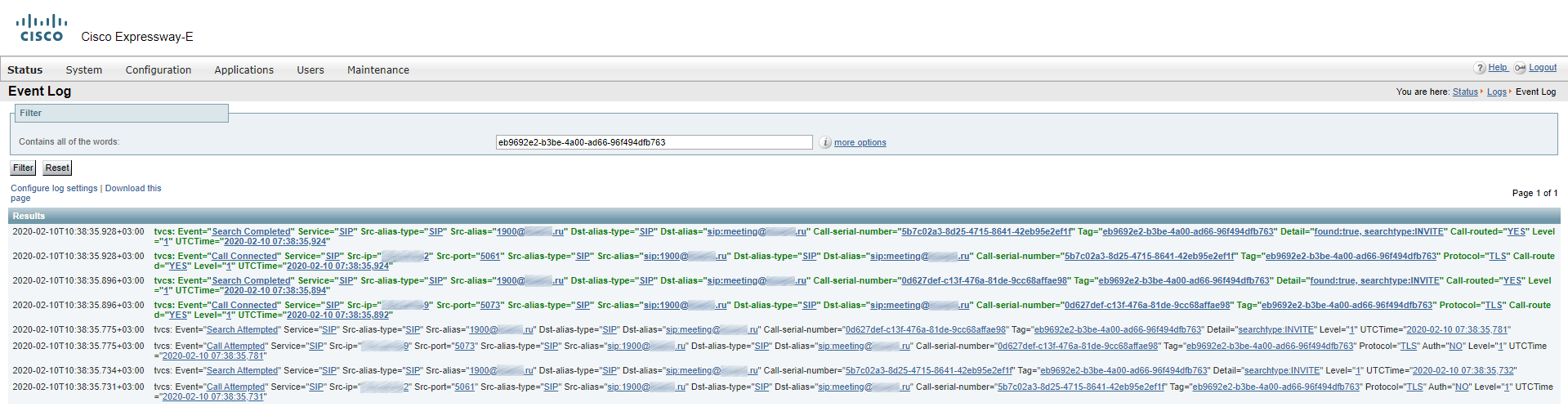
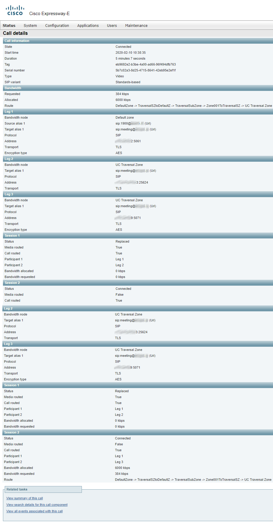
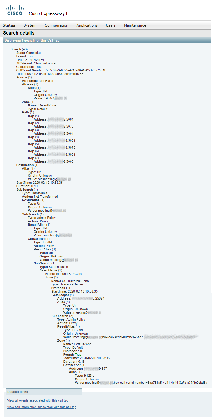
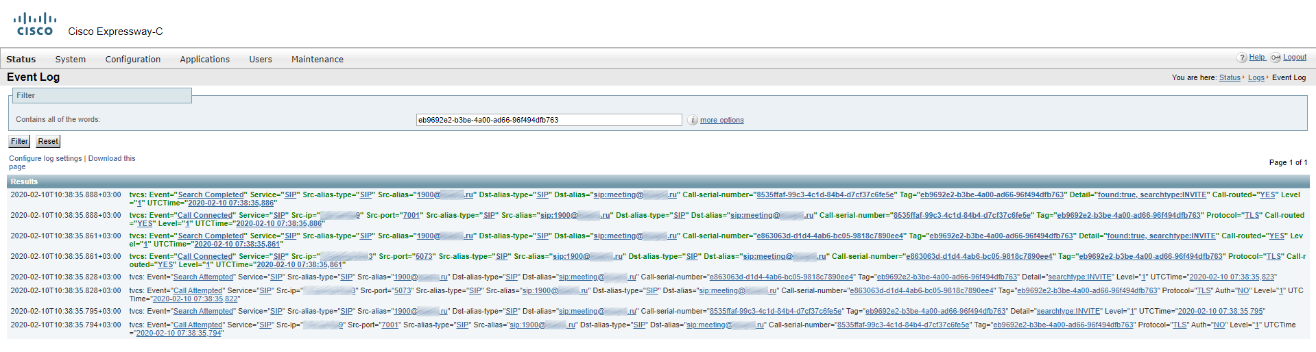
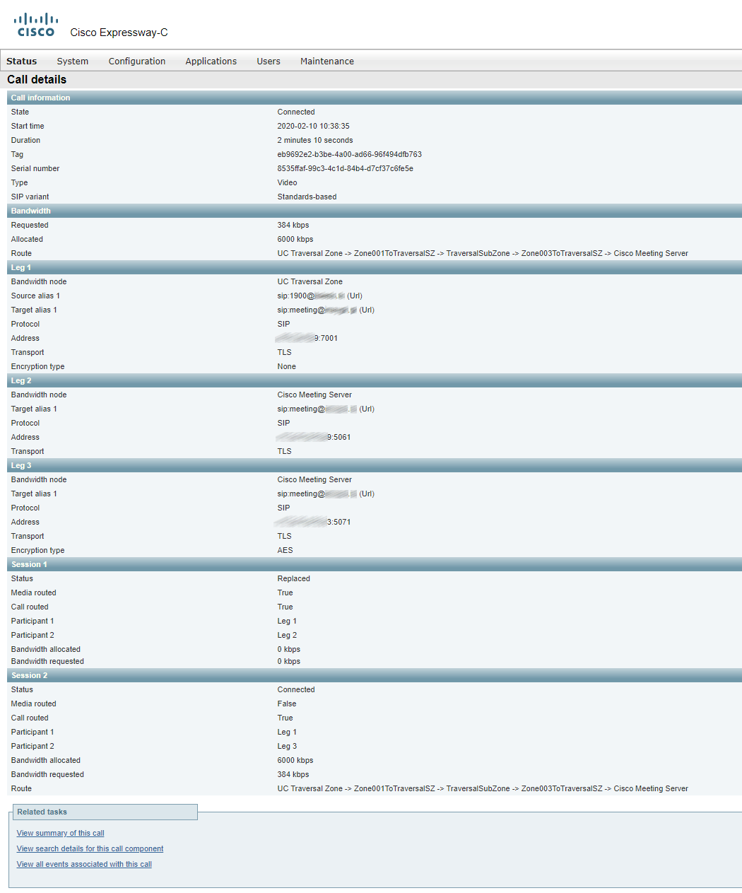
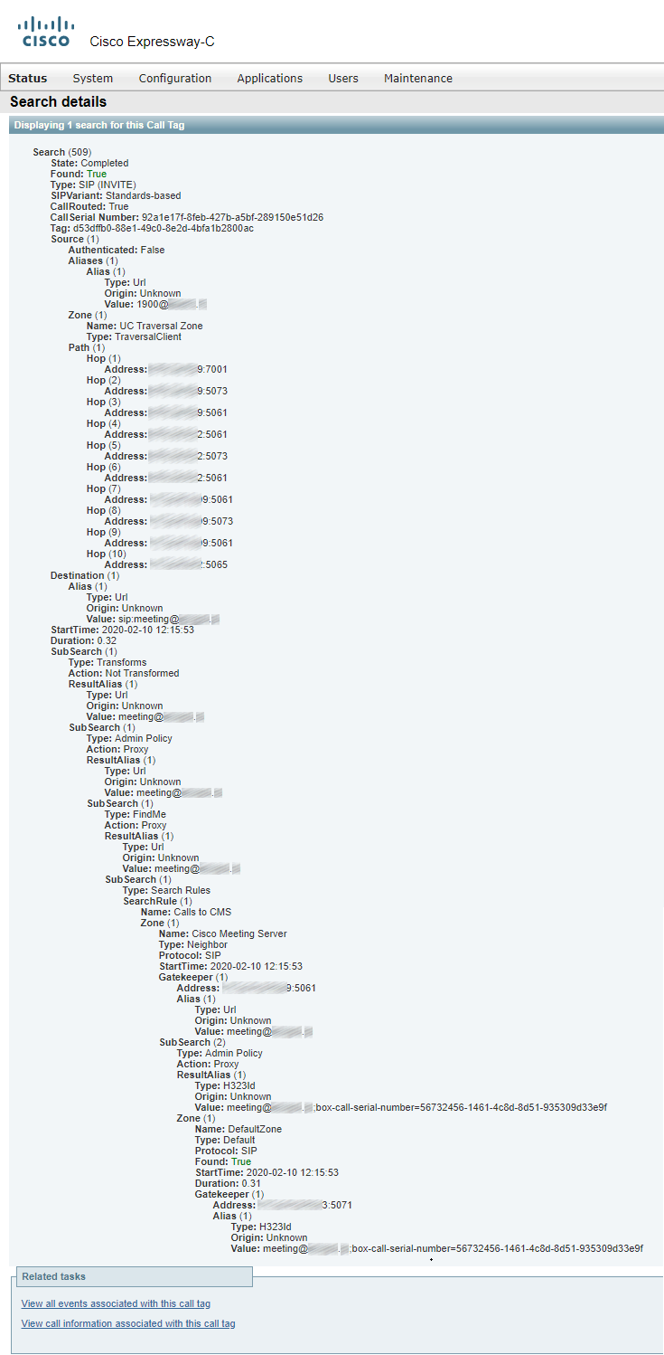
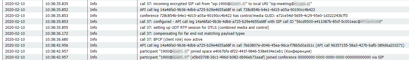
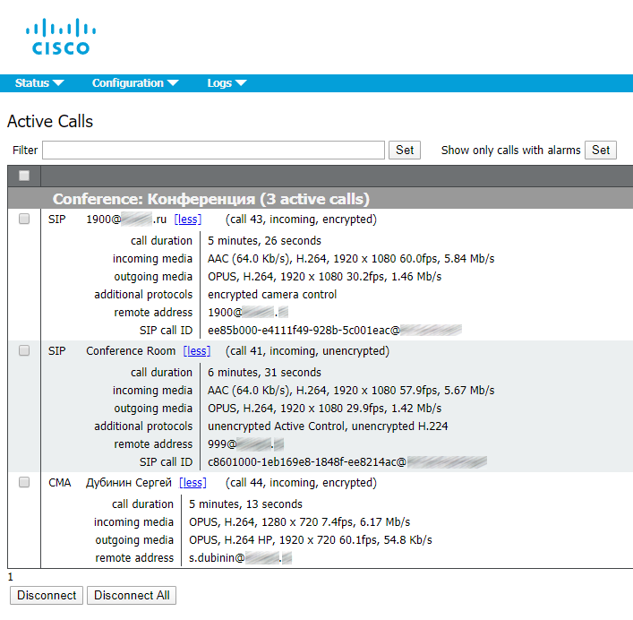


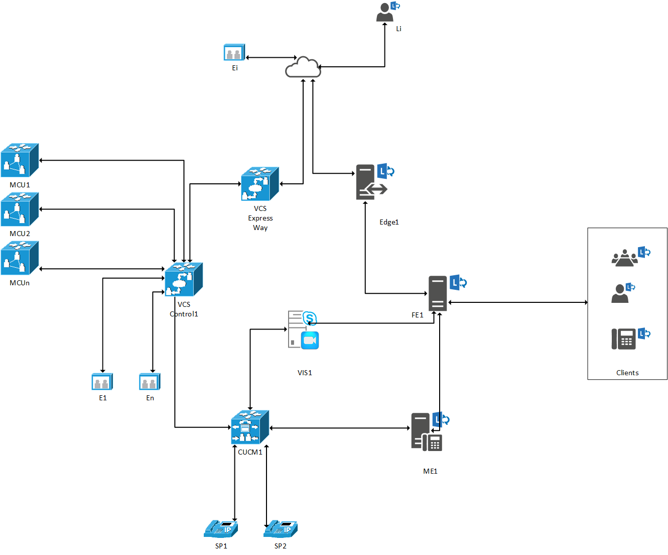
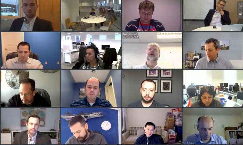
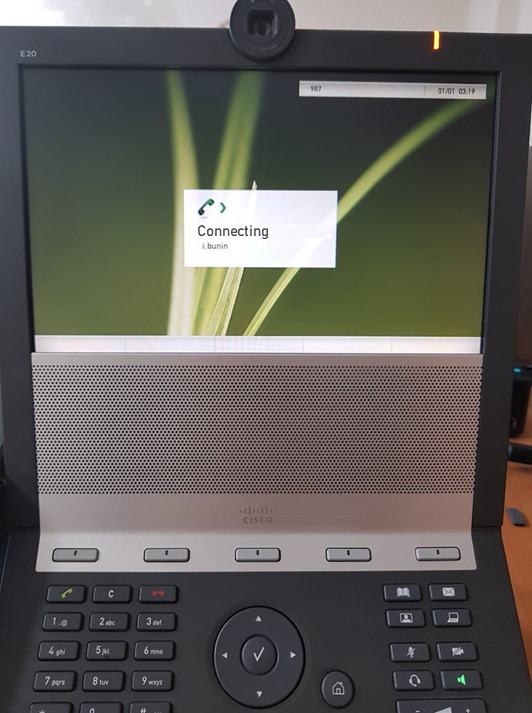
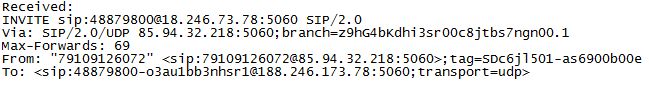
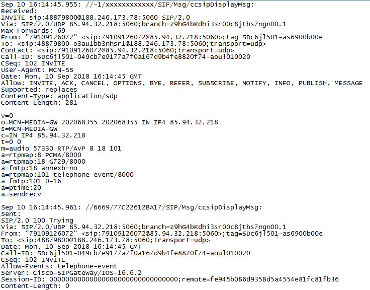
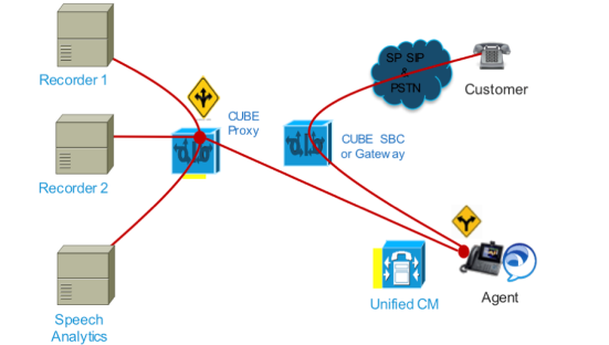
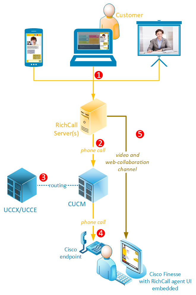 1. A customer initiates an online call


 This article presents a small set of commands for Cisco Voice Operation System (VOS) based servers. These commands help to reveal most problems caused by the platform. Each command comes with a brief description. The most important output data is marked with bold.


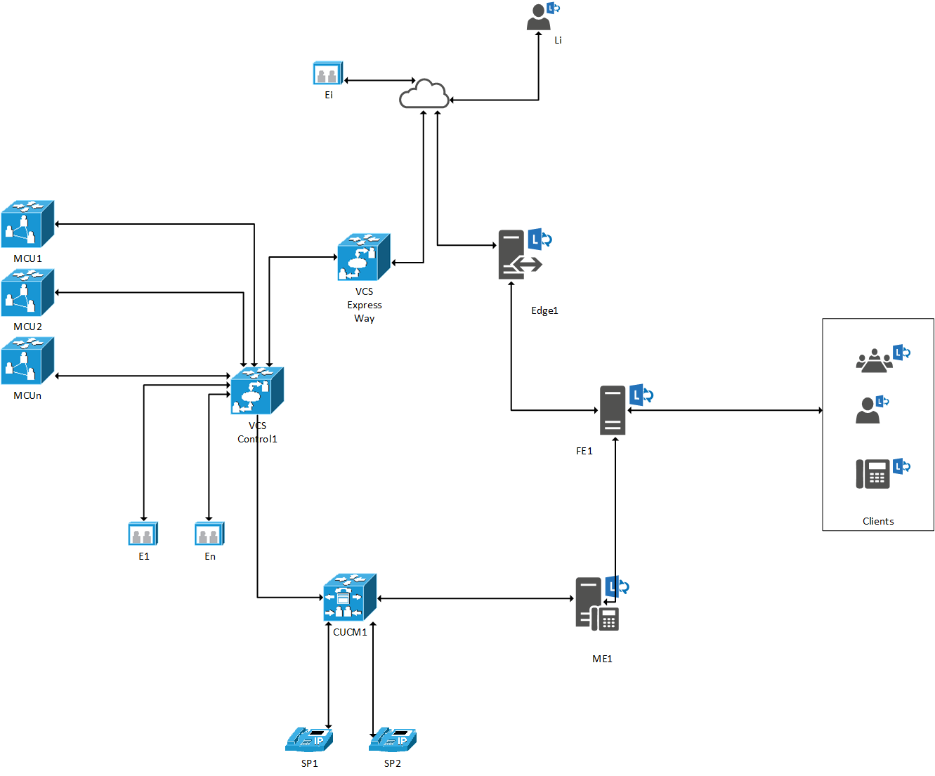
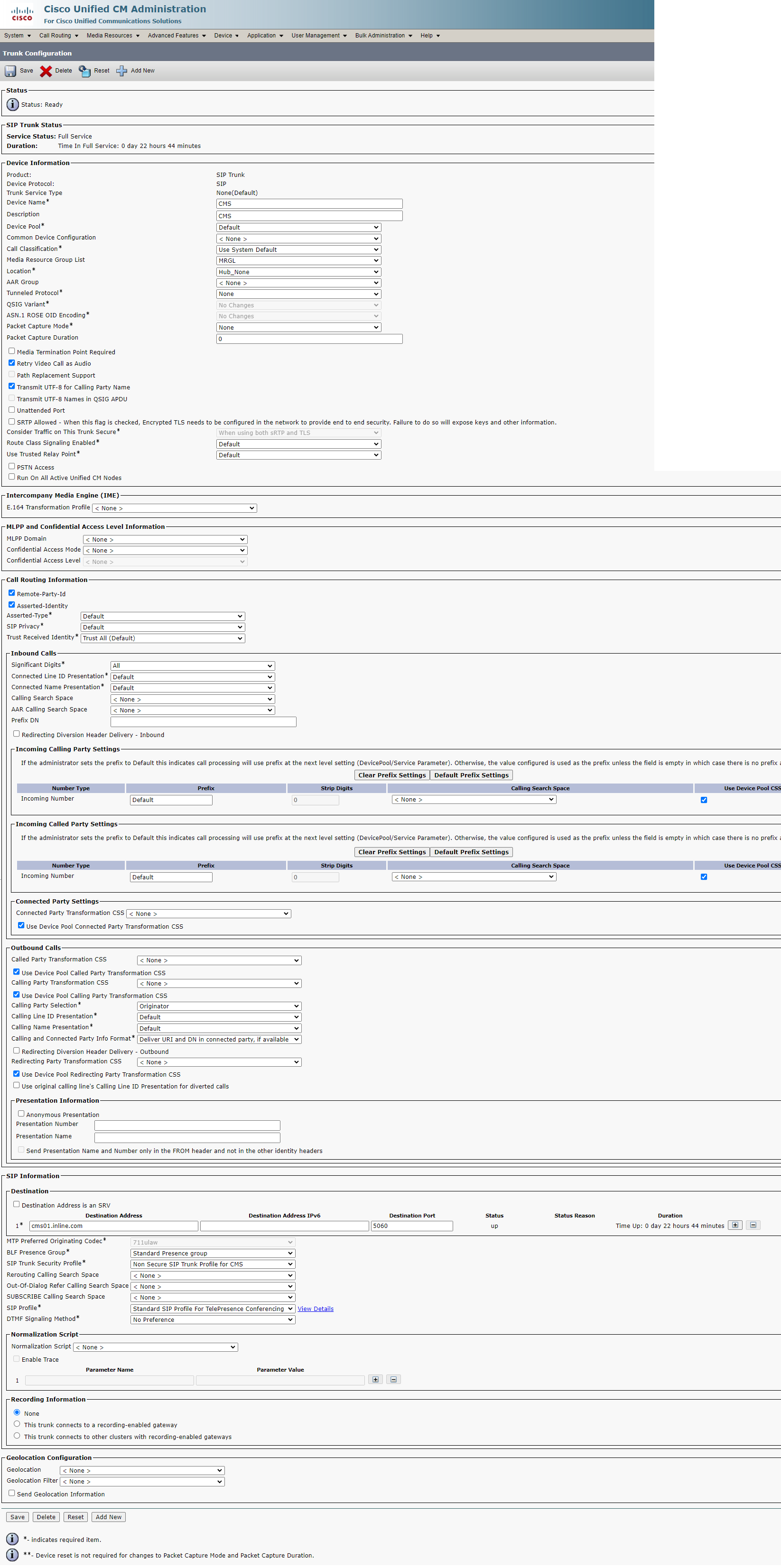
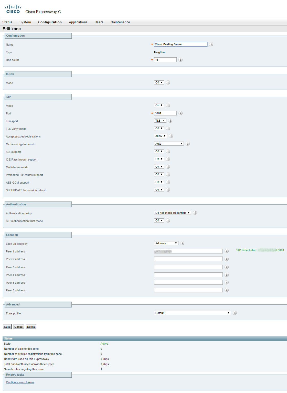
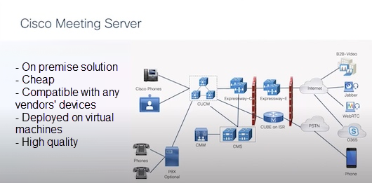
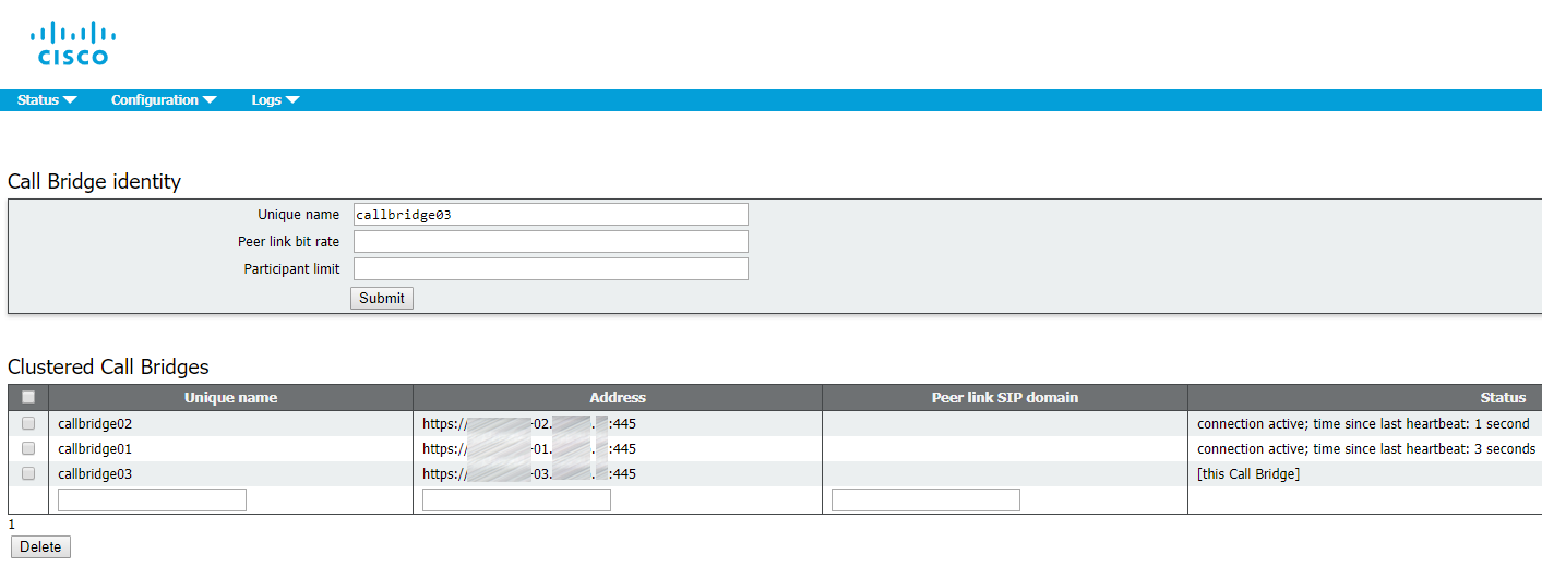
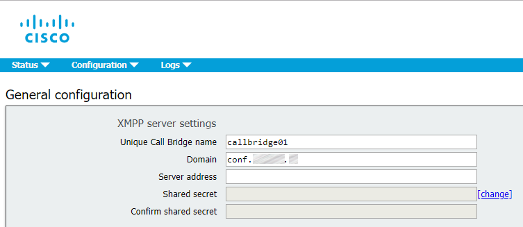
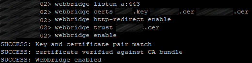
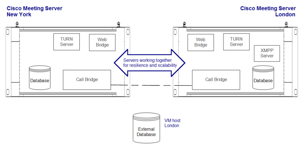
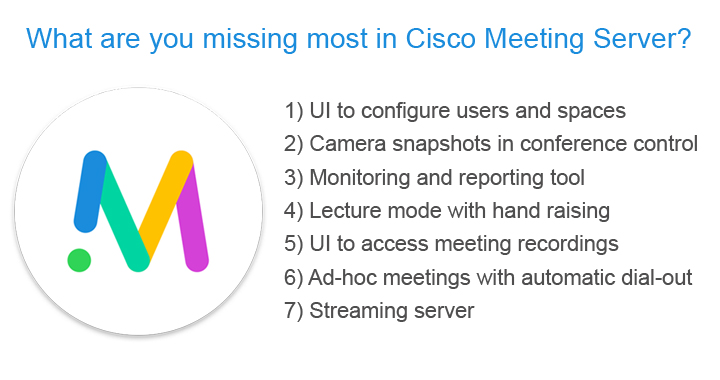
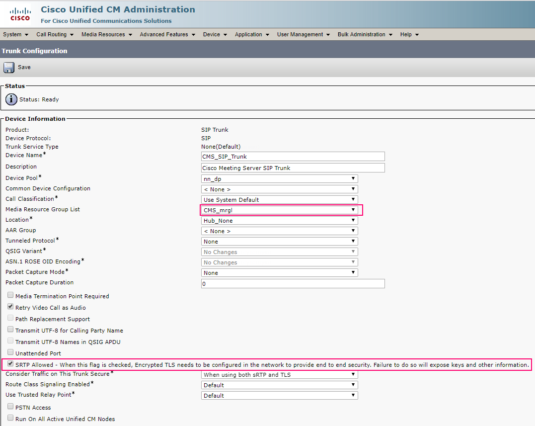
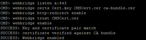
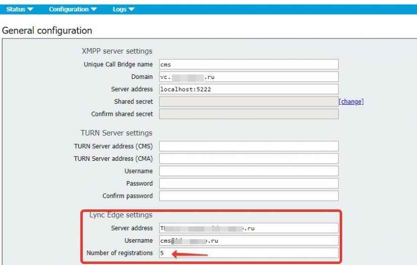
 Acano, acquired by Cisco in Nov 2015, is the best known of its truly interoperable video/audio bridge. On my opinion, this bridge was the primary Cisco's target and Acano is going to replace Cisco Telepresence Server and Conductor in Cisco's business video offering.